High-strength special steel

A high-strength and special technology, applied in the directions of stirring device, separation method, charging treatment type, etc., can solve the problems of waste of resources, comprehensive heating of raw materials, high cost, etc., and achieve the effect of improving cleaning and improving permeability.

Pending Publication Date: 2020-11-13
胡超红
View PDF6 Cites 0 Cited by
  • Summary
  • Abstract
  • Description
  • Claims
  • Application Information

AI Technical Summary

Problems solved by technology

[0003] Most of the hot-melt devices in the prior art put the raw materials into the hot-melt device to heat and melt them. Since the raw materials are piled up in the hot-melt device, the raw materials cannot be fully heated, which will reduce the hot-melt efficiency of the raw materials, and at the same time In the process of hot melting of raw materials, the performance and quality of the steel are reduced due to impurities in the molten iron. At present, the method of removing impurities in the hot melting device is to manually use a filter to remove impurities from the molten iron. However, this method has great safety Hidden danger
[0004] There are also some schemes about special steel in the prior art, such as patent number 201910678702.8, which is named as a patent for high-strength special steel and its processing method. This technical scheme uses a variety of new metal raw materials, and the steel produced has higher strength. and strong anti-extrusion ability, but the raw materials used in this scheme are all new metal raw materials, which not only costs a lot, but also wastes resources

Method used


Image

  • High-strength special steel
  • High-strength special steel
  • High-strength special steel

Examples


Embodiment Construction

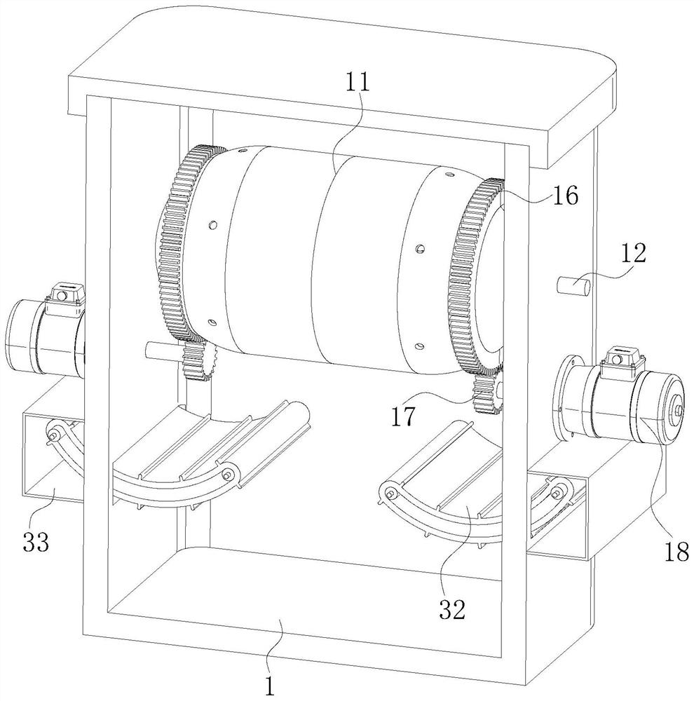
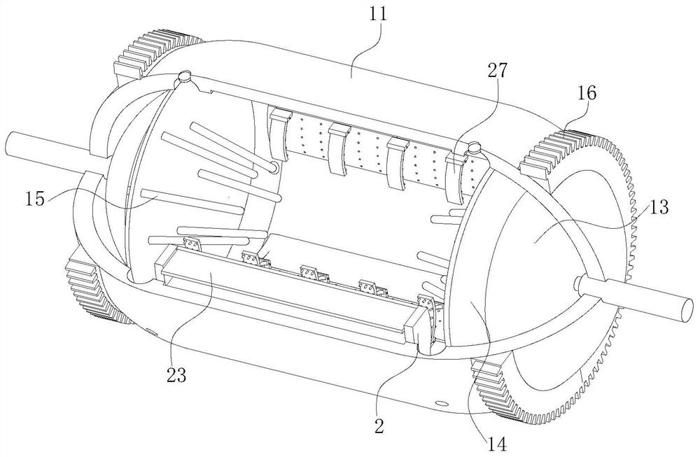
[0036] use Figure 1-Figure 7 A high-strength special steel material according to an embodiment of the present invention will be described as follows.

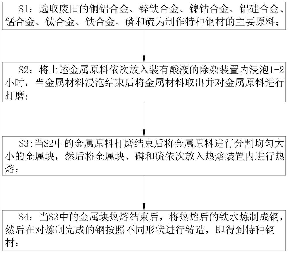
[0037] like Figure 1-Figure 7 Shown, a kind of high-strength special steel of the present invention, the manufacture method of this special steel comprises the following steps:

[0038] S1: Select waste copper-aluminum alloy, zinc-iron alloy, nickel-cobalt alloy, aluminum-silicon alloy, manganese alloy, titanium alloy, iron alloy, phosphorus and sulfur as the main raw materials for making special steel; Resources, improve the utilization value of materials;

[0039] S2: Put the above-mentioned metal raw materials into the impurity removal device equipped with acid solution and soak for 1-2 hours. After the metal material is soaked, take out the metal material and polish the metal raw material; Impurities and rust on the surface of raw materials are cleaned up, so that the quality and performance of special steel can be imp...


PUM


Abstract

The invention belongs to the technical field of special steel, and particularly relates to high-strength special steel. A hot melting device comprises a hot melting bin. The upper end face of the hotmelting bin is connected with a box cover in a sleeved manner. A hot melting box is arranged below the box cover. Supporting columns are rotationally connected in the inner walls of the two sides of the hot melting box. The outer surface of the hot melting box is fixedly connected with evenly-arranged gear discs. The positions, on the end faces of the two sides of the hot melting bin, of the lowerpotions of the two gear discs are fixedly connected with gear shafts through supporting rods, and the gear shafts are engaged with the gear discs. The high-strength special steel is mainly used for solving the problems that in most existing hot melting devices, raw materials are placed into the hot melting devices to be heated and subjected to hot melting, due to the fact that the raw materials are accumulated in the hot melting devices, the raw materials cannot be heated comprehensively, consequently, the hot melting efficiency of the raw materials is reduced, meanwhile, in the hot melting process of the raw materials, due to the fact that impurities are included in molten iron, the performance and quality of the steel are reduced, the manner of manually carrying out impurity remove on filter screens is adopted as the impurity removal manner of the existing hot melting devices, but great potential safety hazards exist in the manner.

Description

technical field [0001] The invention belongs to the technical field of special steel, in particular to a high-strength special steel. Background technique [0002] Steel products are widely used and have various varieties. According to the different cross-sectional shapes, steel products are generally divided into four categories: profiles, plates, pipes and metal products. Steel is a material of a certain shape, size and performance made of steel ingots, billets or steel through pressure processing. Most steel processing is through pressure processing, which causes plastic deformation of the processed steel (billet, ingot, etc.). According to the different processing temperature of steel, it can be divided into two types: cold processing and hot processing. Special steel is different from traditional steel. Use in harsh environments. It is mostly used in special industries. For the introduction of special steel, please refer to the periodical: Various special steel, elec...

Claims


Application Information

Patent Timeline
IPC IPC(8): C22C33/06F27B14/02F27B14/08F27D3/15F27D27/00B01D33/11B01D33/54
CPCC22C33/06F27B14/02F27B14/08F27D3/1545F27D27/00B01D33/11B01D33/54F27B2014/004F27B2014/0818F27M2003/13
Inventor 胡超红孙安杰孔玉
Owner 胡超红
Why Eureka
Try Eureka