Landfill leachate and landfill gas collection system and method

A collection system and landfill gas technology, applied in the fields of landfill technology, pipeline system, waterway system, etc., can solve the problems of easily blocking pipelines, affecting the drainage of landfill gas, blocking horizontal collection tube wells, etc. Pipe blockage, convenient daily maintenance, reasonable design effect

Pending Publication Date: 2020-11-17
胡伟儒
View PDF9 Cites 1 Cited by
  • Summary
  • Abstract
  • Description
  • Claims
  • Application Information

AI Technical Summary

Problems solved by technology

[0004] 1. After the horizontal pipeline has been used for a period of time, due to the sinking of the garbage pile, the leachate in the pile cannot be discharged from the horizontal pipe well, which blocks most of the horizontal collection pipe well; or the leachate is blocked at the turning point of the horizontal well and cannot be discharged in time. dredge;
[0005] 2. The water content of the landfill gas in the garbage dump is very high. At the same time, the internal temperature of the dump is about 45°C. After the gas extracted from the dump is cooled down, a large amount of condensed water will be generated. The condensed water is also easy to block the pipeline and affect the landfill gas. pumping
[0006] Due to the above defects, the pipeline needs to be frequently inspected, maintained and dredged to prevent the leakage of leachate and condensed water and cause environmental risks. It is difficult to maintain and seriously affects the collection and treatment of leachate and landfill gas in the landfill.

Method used


Image

  • Landfill leachate and landfill gas collection system and method
  • Landfill leachate and landfill gas collection system and method

Examples


Embodiment Construction

[0026] The present invention will be further described below in conjunction with the accompanying drawings.

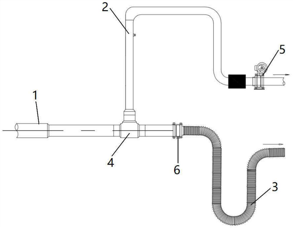
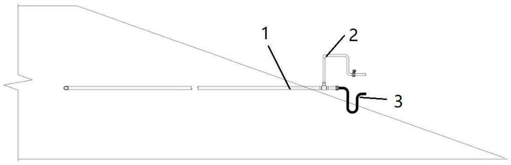
[0027] Such as Figure 1 ~ Figure 2 shown, as Figure 1 ~ Figure 2 As shown, the landfill leachate and landfill gas collection system described in this embodiment includes a first air duct 1, a second air duct 2 and a water duct 3, and the first air duct 1 is inclined relative to the horizontal direction Angle setting, one end of the first air guide pipe 1 extends into the landfill, and the second air guide pipe 2 and the water guide pipe 3 are respectively connected to one end of the first air guide pipe 1 that does not extend into the landfill, The second air guide tube 2 is located between the first air guide tube 1 and the water guide tube 3, and the first air guide tube 1, the second air guide tube 2 and the water guide tube 3 communicate with each other, so The second air guide tube 2 is arranged vertically, and the second air guide tube 2 is connected to a mic...


PUM

PropertyMeasurementUnit
Angleaaaaaaaaaa
Lengthaaaaaaaaaa

Abstract

The invention relates to the field of garbage disposal, in particular to a landfill leachate and landfill gas collection system and method. The landfill leachate and landfill gas collection system comprises a first gas guide pipe, a second gas guide pipe and a water guide pipe. The first gas guide pipe is arranged in an inclined-angle manner relative to the horizontal direction, the second gas guide pipe is located between the first gas guide pipe and the water guide pipe, the first gas guide pipe, the second gas guide pipe and the water guide pipe are communicated with one another, the secondgas air guide pipe is arranged in the vertical direction, and a water seal part is arranged in the water guide pipe. The first gas guide pipe is arranged in the inclined-angle manner, leachate in a landfill waste heap body can flow out of the waste heap body through the gradient, and is convenient to collect; and according to the collection method, the leachate flows through the obliquely-arranged first gas guide pipe firstly, landfill gas enters the second gas guide pipe and is discharged and collected, the leachate flows into the water guide pipe and is collected after overflowing through the water seal part arranged on the water guide pipe, the collection method is convenient to operate, and collection is easy.

Description

technical field [0001] The invention relates to the technical field of garbage treatment, in particular to a landfill leachate and landfill gas collection system and method. Background technique [0002] During the process of landfilling, precipitation, self-contained water in the garbage and other reasons cause the pollutants in the garbage to precipitate together with the water, thus forming landfill leachate. The concentration of organic matter and ammonia nitrogen in landfill leachate is relatively high, and there are many kinds of pollutants. If leachate is discharged directly into the environment without treatment, it will not only pollute water resources, but even pollute soil, crops, aquatic animals, etc., seriously threatening human health. Therefore, it is necessary to treat the landfill leachate to make the effluent quality meet the discharge standard. [0003] At present, for the drainage of leachate and landfill gas in domestic waste piles, most of them flow o...

Claims


Application Information

Patent Timeline
IPC IPC(8): B09B1/00E03F1/00F17D1/02F17D1/08F16L55/24
CPCB09B1/004E03F1/00F17D1/02F17D1/08F16L55/24Y02W30/30
Inventor 胡伟儒何依文
Owner 胡伟儒
Why Eureka
Try Eureka