Melt-blown fabric hydro electret production line

A technology of melt-blown cloth and production line, which is applied in spraying/spraying textile material treatment, processing textile material carrier, removing liquid/gas/steam, etc., and can solve problems such as roughness of melt-blown cloth, less electret, and high risk factor , to achieve the effect of preventing offset and loosening

Pending Publication Date: 2020-11-17
青岛斯凯孚传动机械有限公司
View PDF3 Cites 7 Cited by
  • Summary
  • Abstract
  • Description
  • Claims
  • Application Information

AI Technical Summary

Problems solved by technology

The current electret process adopts the corona electret method, which produces less electret, low electrostatic adsorption strength, high voltage corona electret, ionized ozone affects the environment, and has a large risk factor. The effect is not ideal; and the water electret production line in the prior art electrets the melt-blown cloth, the surface of the melt-blown cloth after "spraying and charging" is easy to fluff, resulting in rougher melt-blown cloth after processing, affect the quality of its processing into other products

Method used


Image

  • Melt-blown fabric hydro electret production line
  • Melt-blown fabric hydro electret production line
  • Melt-blown fabric hydro electret production line

Examples


specific Embodiment approach 1

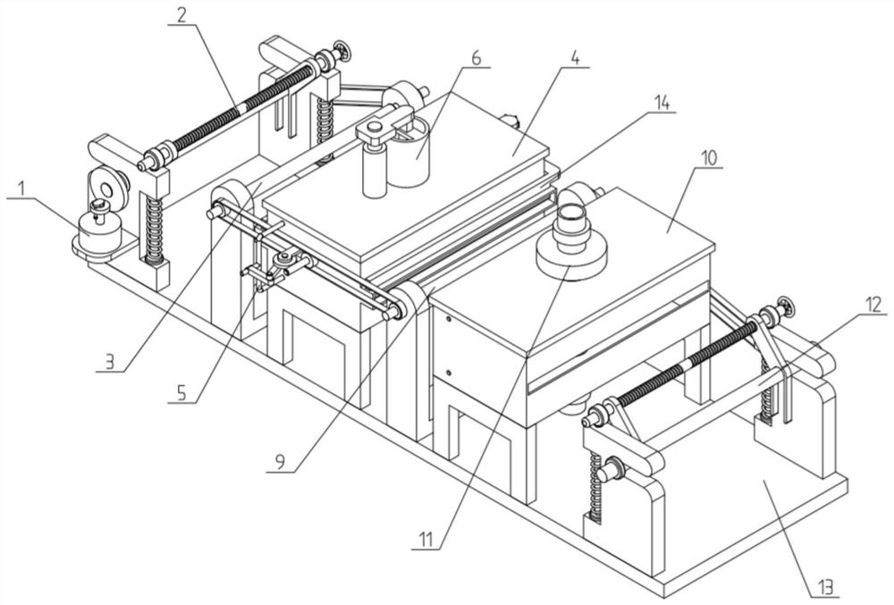
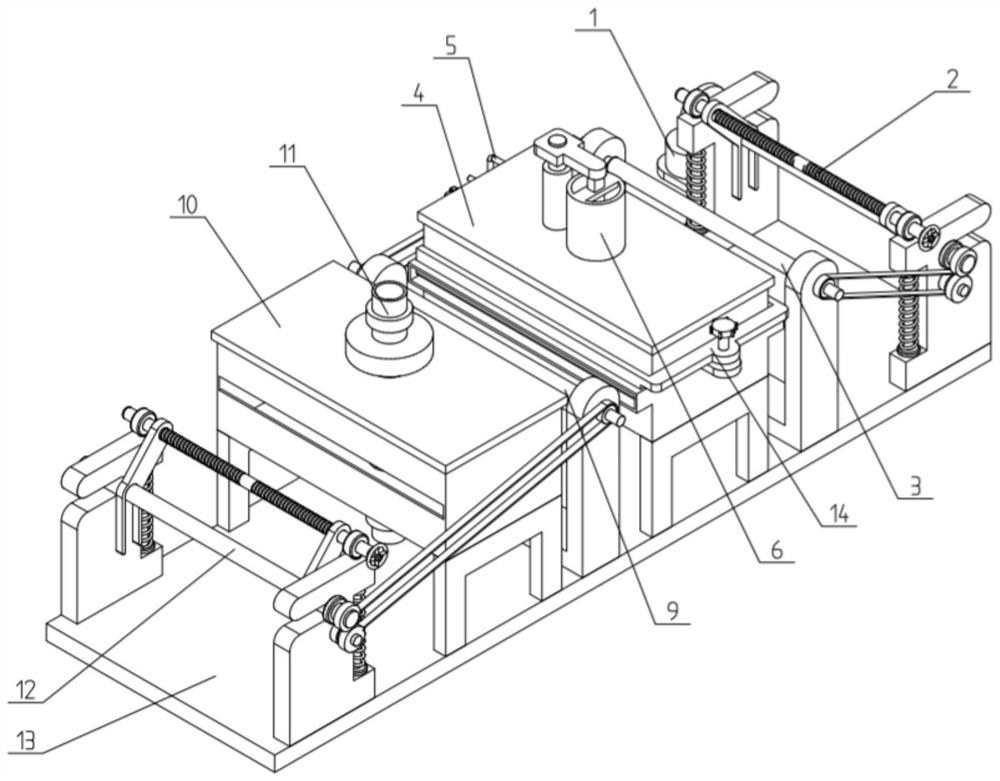
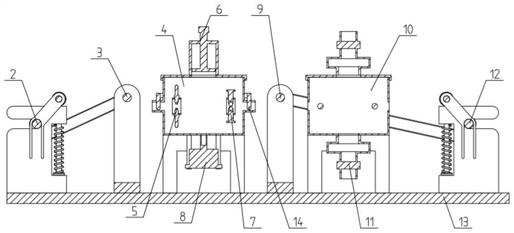
[0040] Such as Figure 1-13 As shown, the meltblown water electret production line includes a driving mechanism 1, an unwinding mechanism 2, a leading fabric guiding mechanism 3, an electret box 4, a spunlace electret mechanism 5, a pressure regulating mechanism 6, a rolling mechanism 7, and a return water Collecting box 8, rear fabric guide mechanism 9, drying box 10, hot air blower 11, winding mechanism 12 and base 13, the driving mechanism 1 is connected on the described unwinding mechanism 2, and the driving mechanism 1 is connected to the described The unwinding mechanism 2; the unwinding mechanism 2, the front cloth guide mechanism 3, the electret box 4, the rear cloth guide mechanism 9, the drying box 10 and the winding mechanism 12 are installed on the base 13 in sequence from front to back; The front and rear ends of the inside of the electret box 4 are respectively connected to the spunlace electret mechanism 5 and the rolling mechanism 7; the pressure regulating mec...

specific Embodiment approach 2

[0043] Such as Figure 1-13 As shown, the unwinding mechanism 2 includes a side frame 201, a cloth roller 202, a side stop ring 203, a first gear 204, a second gear 205, a first pulley 206, a wheel shaft one 207 and a tension adjustment assembly; The two ends of the distribution roller 202 are plugged into the two front slots of the two side frames 201; the two ends of the distribution roller 202 are respectively fixed with a side stop ring 203, and the two side stop rings 203 are rolled and fitted on the two sides. On the outer side of the frame 201; one end of the distribution roller 202 is connected to the drive mechanism 1; the other end of the distribution roller 202 is fixedly connected to the first pulley 206 and the first gear 204, and the first gear 204 is meshed with the transmission connection The second gear 205; the second gear 205 and the first pulley 206 are all fixed on the wheel shaft one 207; the wheel shaft one 207 is rotatably connected to a side frame 201;...

specific Embodiment approach 3

[0046] Such as Figure 1-13 As shown, the drive mechanism 1 includes a servo motor 101 with a reducer, a drive shaft 102, a friction transmission wheel 103, a friction linkage wheel 104, a rotating plate 105 and a first screw 106; the servo motor 101 is fixed by a motor bracket Connected on a side frame 201; the output shaft of the servo motor 101 is connected to the drive shaft 102 through a coupling; the friction drive wheel 103 is slidingly fitted on the drive shaft 102; the top end of the drive shaft 102 is fixedly connected One end of the rotating plate 105; the other end of the rotating plate 105 is rotated and connected to the upper end of the first screw 106; the middle of the first screw 106 is threaded on the friction transmission wheel 103 to drive the The friction transmission wheel 103 slides up and down on the drive shaft 102 ; the friction transmission wheel 103 is vertically frictionally connected to the friction linkage wheel 104 ; the friction linkage wheel 1...


PUM


Abstract

The invention relates to the field of melt-blown fabric production equipment, and in particular relates to a melt-blown fabric hydro electret production line that comprises a driving mechanism, an unwinding mechanism, a front fabric guide mechanism, an electret box, a spunlace electret mechanism, a pressure adjusting mechanism, a rolling mechanism, a return water collecting box, a rear fabric guide mechanism, a drying box, an air heater, a winding mechanism and a base, wherein the driving mechanism is connected to the unwinding mechanism and is in transmission connection with the unwinding mechanism; the unwinding mechanism, the front fabric guide mechanism, the electret box, the rear fabric guide mechanism, the drying box and the winding mechanism are sequentially installed on the base from front to back; the front end and the rear end of the interior of the electret box are connected with the spunlace electret mechanism and the rolling mechanism correspondingly; the rolling mechanismis arranged in the melt-blown fabric hydro electret production line, and after spunlace electret is formed on the melt-blown fabric, flattening treatment can be carried out on the surface of the melt-blown fabric through the rolling mechanism, so that the surface of the melt-blown fabric is more compact and smooth, and the situation that the surface of the melt-blown fabric is rough and fluffed and thus the product quality is affected is prevented.

Description

technical field [0001] The invention relates to the field of melt-blown cloth production equipment, more specifically, to a melt-blown cloth water electret production line. Background technique [0002] Melt-blown non-woven fabrics are mostly used for air filtration and purification, and are widely used in masks, purifiers, fresh air systems, air filters, etc. Non-woven fabrics need to go through multiple processes during production, among which the quality of the electret process Will directly affect the quality of the product. The current electret process adopts the corona electret method, which produces less electret, low electrostatic adsorption strength, high voltage corona electret, ionized ozone affects the environment, and has a large risk factor. The effect is not ideal; and the water electret production line in the prior art electrets the melt-blown cloth, the surface of the melt-blown cloth after "spraying and charging" is easy to fluff, resulting in rougher melt...

Claims


Application Information

Patent Timeline
Patent Type & Authority Applications(China)
IPC IPC(8): D06B1/02D06B23/04D06B15/00D06B23/20D06C15/00
CPCD06B1/02D06B23/04D06B15/00D06B23/20D06C15/00
Inventor 刘鹏举
Owner 青岛斯凯孚传动机械有限公司
Why Eureka
Try Eureka