Method for establishing PEEK composite material fiber laying heat transfer model

A composite material fiber and transfer model technology, applied in special data processing applications, instruments, electrical digital data processing, etc., can solve problems such as difficulty in accurately reflecting temperature field changes, and achieve good prediction results

Pending Publication Date: 2020-11-17
JIANGSU UNIV OF TECH
View PDF2 Cites 0 Cited by
  • Summary
  • Abstract
  • Description
  • Claims
  • Application Information

AI Technical Summary

Problems solved by technology

[0004] In order to achieve the above purpose, the present invention provides a method for establishing a PEEK composite fiber laying heat transfer model to solve the problem that the heat transfer model is difficult to accurately reflect the complex temperature field changes inside the layup during the automatic laying process of thermoplastic fibers

Method used

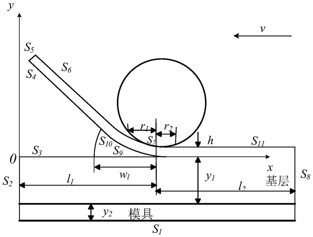
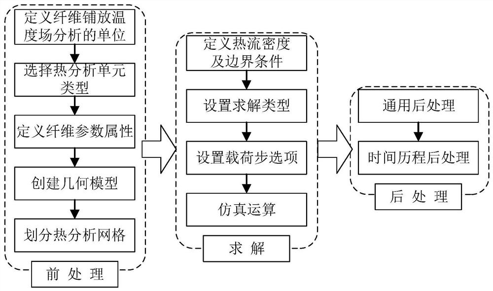

Image

  • Method for establishing PEEK composite material fiber laying heat transfer model
  • Method for establishing PEEK composite material fiber laying heat transfer model
  • Method for establishing PEEK composite material fiber laying heat transfer model

Examples


Embodiment Construction

[0017] In order to understand the characteristics and technical content of the present invention in more detail, the implementation of the present invention will be described in detail below in conjunction with the accompanying drawings. The attached drawings are only for reference and description, and are not intended to limit the present invention.

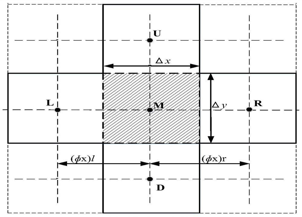
[0018] figure 1 A schematic diagram of the control unit of the two-dimensional model of the thermoplastic fiber filament provided by the embodiment of the present invention; in the figure: heat will be transferred from one unit to its adjacent upper, lower, left, and right units, and point M in the figure represents the middle unit body, such as the dotted line As shown, point L represents the left unit of the middle unit body, point R represents the right unit of the middle unit body, point U represents the upper unit of the middle unit body, and point D represents the lower unit of the middle unit body.

[0019] figure 2 A s...


PUM


Abstract

The invention provides a method for establishing a PEEK composite material fiber placement heat transfer model. The method comprises the following steps: defining a fiber placement temperature field analysis unit in a pretreatment module, selecting a thermal analysis unit type, establishing a geometric model, defining thermoplastic fiber and mold material related attributes, and dividing thermal analysis grids at equal intervals; defining a heat flow density load and a heat dissipation boundary condition in a solving module, and setting a load step option; establishing a geometric model by utilizing an ANSYS finite element analysis software cyclic loading technology and a birth-death unit, applying an initial temperature and a boundary condition, killing all the layering units, activatingthe bth unit of the a layer, applying a thermal load to an activation unit to delete the thermal load of the previous load step, and repeating the steps; solving the transient process of the temperature field, carrying out equidistant grid division on the thickness and length directions of the base layer of the paving layer, and dividing two units in the thickness direction of each layer; and setting a command stream through the APDL, and completing the establishment of a related model.

Description

technical field [0001] The invention relates to a heat transfer model technology, in particular to a method for establishing a PEEK composite material fiber laying heat transfer model. Background technique [0002] Fiber-reinforced composite materials have the advantages of light weight, high specific strength and specific modulus, no reflection of electromagnetic waves, and large design freedom. They have become the preferred materials for aerospace components and large passenger aircraft. Due to the characteristics of stable quality and high molding efficiency (about 5 to 20 times the efficiency of manual laying), the automatic lay-up molding technology has been applied in foreign aircraft manufacturing enterprises. The use of fiber-reinforced composite materials can reduce the weight of the aircraft itself, reduce fuel consumption, and improve the overall performance of the aircraft. [0003] The in-situ curing technology is adopted in the thermoplastic fiber laying proc...

Claims


Application Information

Patent Timeline
Patent Type & Authority Applications(China)
IPC IPC(8): G06F30/23G06F113/26G06F119/08
CPCG06F30/23G06F2113/26G06F2119/08
Inventor 曹忠亮林国军李海龙王明成佟苗余乐富宏亚韩振宇
Owner JIANGSU UNIV OF TECH
Why Eureka
Try Eureka