A waste heat recovery system

A waste heat recovery system and exhaust gas technology, applied in the field of waste heat recovery, can solve the problem of low utilization rate of waste heat and achieve the effect of improving the utilization rate

Active Publication Date: 2022-02-11
NINGBO HONGJING ENVIRONMENTAL PROTECTION TECH
View PDF6 Cites 0 Cited by
  • Summary
  • Abstract
  • Description
  • Claims
  • Application Information

AI Technical Summary

Problems solved by technology

At present, the heat after combustion is carried out by the gas and exchanges heat with the exhaust gas to be burned, and part of the heat is recovered and utilized, so there is a problem that the utilization rate of waste heat is not high

Method used


Image

  • A waste heat recovery system
  • A waste heat recovery system

Examples


Embodiment 1

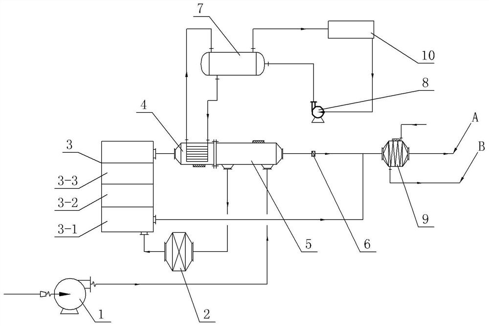
[0023] Embodiment one is basically as attached figure 1 , 2 Shown: as figure 1 The exhaust gas waste heat recovery system shown includes fan 1, flame arrester 2, catalytic oxidation bed 3, waste heat furnace 4, preheater 5, heat exchanger 9, steam drum 7, water pump 8 and pipelines. The preheater 5 includes a waste gas inlet, a waste gas outlet, a gas inlet and a gas outlet. The fan 1 communicates with the waste gas inlet of the preheater 5 through a pipeline, and the flame arrester 2 communicates with the waste gas outlet of the preheater 5 through a pipeline.

[0024] Catalytic oxidation bed 3 includes heat exchange section 3-1, heating section 3-2 and catalytic section 3-3, flame arrester 2, heat exchange section 3-1, heating section 3-2, catalytic section 3-3, waste heat furnace 4 , the gas inlet of the preheater 5 and the heat exchanger 9 are connected through pipelines in sequence, and a control valve 6 is installed on the pipeline between the preheater 5 and the heat ...

Embodiment 2

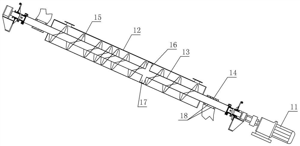
[0032] On the basis of Example 1, as figure 1 The shown heat exchange section 3-1 is provided with a heat exchange mechanism, such as figure 2 As shown, the heat exchange mechanism includes a servo motor 11, a hot gas pipe 12, a waste gas pipe 13 and two connecting pipes 14. The hot gas pipe 12 is obliquely fixed in the heat exchange section 3-1 by bolts, and the upper end of the hot gas pipe 12 passes through the internal channel. It communicates with the catalytic section 3-3, and the lower end of the hot gas pipe 12 communicates with the heat exchanger 9 through a pipeline.

[0033] The servo motor 11 is fixed and installed in the heat exchange section 3-1 by bolts. The model of the servo motor 11 can be selected as MR-J2S-100A. The side walls of the oxidation bed 3 are rotatably connected, and the waste gas pipe 13 is rotatably arranged in the hot gas pipe 12 .

[0034]The waste gas pipe 13 is welded with a helical piece 15 and a collection plate 16 , and the collection...

Embodiment 3

[0042] On the basis of Example 2, such as figure 2 As shown, in this embodiment, the inclination angle of the hot gas pipe 12 is 30°, the collecting pan 16 is located at the lower end of the waste gas pipe 13, and the spiral pieces 15 at the upper and lower ends of the waste gas pipe 13 are more sparsely distributed, and the spiral pieces 15 in the middle of the waste gas pipe 13 The spacing distribution is denser. In addition if figure 1 As shown, the waste heat furnace 4 and the preheater 5 are integrated, that is, the tail of the waste heat furnace 4 and the gas inlet of the preheater 5 are directly welded and communicated.


PUM


Abstract

The invention relates to the field of waste heat recovery, in particular to a waste gas waste heat recovery system, which includes a catalytic oxidation bed, a waste heat furnace, a preheater, a heat exchanger and a steam drum. The catalytic oxidation bed includes a heat exchange section, a heating section and a catalytic section. Heater includes exhaust gas outlet and gas inlet, exhaust gas outlet of preheater, heat exchange section, heating section, catalytic section, waste heat furnace, gas inlet of preheater and heat exchanger are connected in sequence, between preheater and heat exchanger There is a control valve between them, the steam drum is connected with the waste heat furnace, and the catalytic section, the heat exchange section are connected with the heat exchanger. When the technical scheme is adopted, it is beneficial to improve the utilization rate of waste heat.

Description

technical field [0001] The invention relates to the field of waste heat recovery, in particular to a waste gas waste heat recovery system. Background technique [0002] The catalytic oxidation process is more commonly used in the treatment of VOC waste gas. This process uses a catalyst to make the organic waste gas undergo flameless combustion at a lower ignition temperature, and decompose the organic waste gas into non-toxic carbon dioxide and water to achieve the purpose of waste gas treatment. At present, the heat after combustion is carried out by the gas and exchanges heat with the exhaust gas to be burned, and part of the heat is recovered and utilized, which has the problem of low utilization rate of waste heat. Contents of the invention [0003] The purpose of the present invention is to provide a recovery system that is beneficial to improving the utilization rate of waste heat after exhaust gas combustion. [0004] In order to achieve the above purpose, the tech...

Claims


Application Information

Patent Timeline
Patent Type & Authority Patents(China)
IPC IPC(8): F22B1/18F23G5/46F23G7/07
CPCF22B1/18F23G5/46F23G7/07F23G2206/203F23G2209/14Y02E20/12
Inventor 李文铃朱海峰
Owner NINGBO HONGJING ENVIRONMENTAL PROTECTION TECH
Why Eureka
Try Eureka