PCB and connector flat pressing type crimping tool

A connector and tooling technology, applied in the direction of electrical components, electrical components, etc., can solve problems such as difficulty in ensuring accurate alignment of relative positional relationships, damage to connectors and printed boards, and a lot of time spent, to achieve flexible and changeable positions , crimping convenience, low cost effect

Active Publication Date: 2020-11-20
10TH RES INST OF CETC
View PDF12 Cites 3 Cited by
  • Summary
  • Abstract
  • Description
  • Claims
  • Application Information

AI Technical Summary

Problems solved by technology

However, manual alignment is difficult to ensure that the relative positional relationship between the lower die, upper die, socket, and printed board is accurately aligned.
Especially when there are multiple connectors on the PCB motherboard, the operator spends a lot of time on alignment. Once the alignment is inaccurate, it will cause damage to the connectors and printed boards, or damage to components and other quality problems.

Method used


Image

  • PCB and connector flat pressing type crimping tool
  • PCB and connector flat pressing type crimping tool
  • PCB and connector flat pressing type crimping tool

Examples


Embodiment Construction

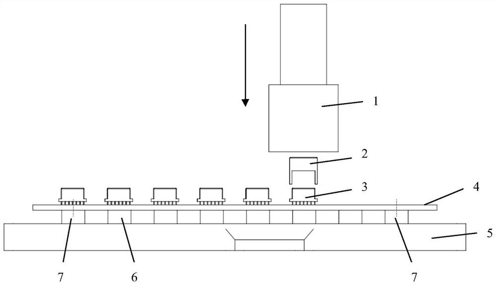
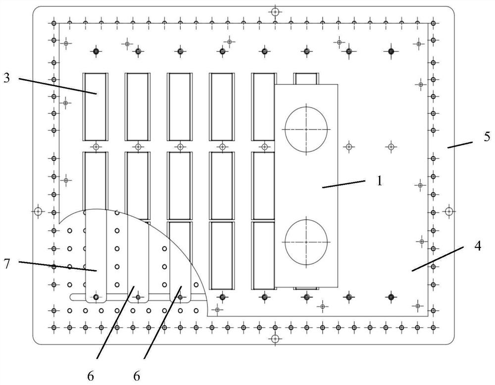
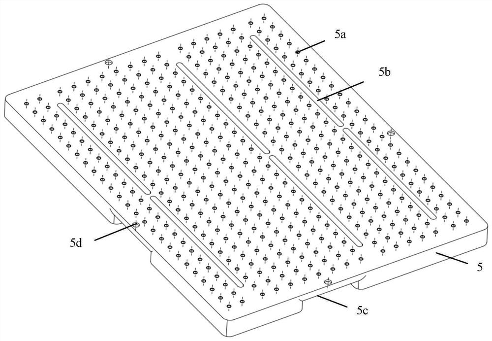
[0029] refer to Figure 1-Figure 8 . In the preferred embodiment described below, a PCB and connector flat pressure crimping tooling includes: the lower die 6 fixed on the lower die positioning plate 5 distributed in the horizontal direction of the strip groove and the lower die 6 and the The upper die 2 between the crimping heads 1 of the crimping machine is characterized in that the lower die positioning plate 5 is provided with a positioning pin 7 for positioning the PCB board 4 and a bar-shaped groove 5b separating a plurality of lower dies 6, and the bar-shaped The groove 5b divides a plurality of lower dies 6 into at least two crimping areas, as the lower dies 6 of the PCB motherboard 4 supports during crimping, and are distributed in the separated crimping areas; according to the PCB motherboard 4 each The length and width of each crimping position are made into a strip-shaped lower die 6, which is formed with a through-threaded hole consistent with the mounting hole o...


PUM


Abstract

The invention discloses a PCB and a connector flat pressing type crimping tool, and aims to provide a crimping tool which is easy to align, rapid and convenient in crimping and high in one-time crimping qualification rate. The technical scheme comprises the steps that a lower die positioning plate provided with a positioning pin and a strip-shaped groove for separating a plurality of lower pressing dies is produced, the strip-shaped groove divides the lower pressing dies into a plurality of crimping areas, and the lower pressing dies are distributed in the separated crimping areas; during crimping, module pins of a connector pass through correspondingly prefabricated metallized plugging holes in a PCB mother board and are arranged in a matrix manner and inserted into the PCB mother board;and according to numerical control programming, a set crimping force and a crimping height, a crimping machine crimping head selects the number of the lower pressing dies on the support surface of thePCB mother board for the connector that has been positioned corresponding to the lower pressing dies to push a lower die positioning plate with an effective press-in force with single-pin pressure which does not exceed 35N to press the pin of the connector into the metallized plugging holes of the PCB mother board so as to complete crimping.

Description

technical field [0001] The invention relates to connector crimping assembly and belongs to the technical field of electrical interconnection assembly. Especially the crimping machine technology is used to install multi-pin crimping connectors on complex printed circuit boards, and the crimping tooling used in the PCB process of printed circuit boards. Background technique [0002] Many electronic devices use connectors, such as for data transmission or charging applications. Among them, printed board components often play a role in signal control and transmission, and in signal transmission, connectors are key transmission devices. The assembly types of connectors on printed boards are mainly divided into ordinary soldering type and crimping type. Each pin on the ordinary soldering connector needs to be soldered one by one by a skilled operator with a soldering iron, which makes quality control difficult. Crimp-type connectors use equipment that can crimp all pins in plac...

Claims


Application Information

Patent Timeline
Patent Type & Authority Applications(China)
IPC IPC(8): H05K13/00H05K13/04
CPCH05K13/0061H05K13/04
Inventor 伍怀兵
Owner 10TH RES INST OF CETC
Why Eureka
Try Eureka