
Flue gas treatment device for asphalt workshop

A flue gas treatment and workshop technology, which is applied in gas treatment, combined device, air quality improvement and other directions, can solve the problems of insufficient purification of flue gas, deposition of pollutants in pipelines, affecting normal emission of flue gas, etc., and achieves increased contact Time and area, avoid impurity accumulation and blockage, and improve the effect of flue gas purification efficiency

Active Publication Date: 2020-11-24
杭州恒基新材料科技有限公司
View PDF8 Cites 1 Cited by
  • Summary
  • Abstract
  • Description
  • Claims
  • Application Information

AI Technical Summary

Problems solved by technology

The existing asphalt flue gas treatment devices are generally treated by simple plate absorption towers, filtration or washing and spraying. There are problems of poor cooling effect and unsatisfactory purification efficiency, and generally the pipes for smoke exhaust treatment are long, and the inside of the pipes is not easy to clean. After a long time, pollutants are prone to deposit and blockage in the pipes, affecting the normal discharge of smoke. Some of the purifiers used to adsorb pollutants are saturated after long-term adsorption and filtration, and it is difficult to take out and clean them in the pipeline, which will affect the subsequent treatment effect, thus failing to fully purify the flue gas.
Therefore, the existing bitumen flue gas treatment device has the problems of unsatisfactory purification efficiency and difficult cleaning inside the pipeline.

Method used


Image

  • Flue gas treatment device for asphalt workshop
  • Flue gas treatment device for asphalt workshop
  • Flue gas treatment device for asphalt workshop

Examples


Embodiment Construction

[0018] The present invention will be further described below in conjunction with the accompanying drawings and embodiments, but not as a basis for limiting the present invention.

[0019] Example.

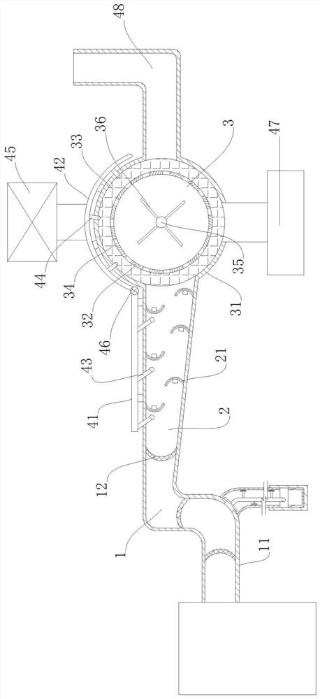
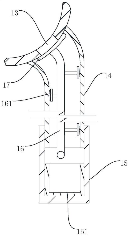
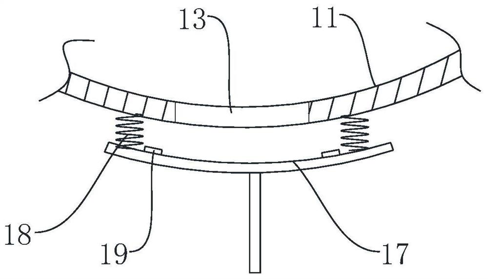
[0020] Such as Figure 1-4 As shown, a flue gas treatment device in an asphalt plant includes a filter area 1, a discharge area 2 and a purification area 3 arranged in sequence. The filter area 1 is composed of a curved pipe 11, and several filter screens are arranged in the pipe 11 12. The bottom bend of the pipeline 11 is provided with a dust outlet 13, and the outside of the bottom bend of the pipeline 11 is provided with a downwardly extending dust discharge pipe 14, and the outside of the dust discharge pipe 14 is provided with a dust discharge pipe 14 The sliding sleeve 15 that moves up and down, the inside of the dust discharge pipe 14 is provided with a connecting rod 16, the lower end of the connecting rod 16 is connected with the sliding sleeve 15, and the upper end of t...


PUM


Abstract

The invention discloses a flue gas treatment device for an asphalt workshop. The flue gas treatment device comprises a filtering region, a discharging region and a purifying region which are sequentially disposed; the filtering region is formed by a bent pipeline, and a filtering screen is arranged in the pipeline; arc baffles distributed up and down in a staggered manner are arranged in the discharging region, discharging bodies are arranged on internal concave surfaces of the arc baffles, and activated carbon is arranged on external convex surfaces of the arc baffles; the purifying region comprises an outer shell and an inner shell, a purifying filler is arranged between the outer shell and the inner shell, the inner shell is provided with through holes, a rotating shaft driven by a motor is arranged in the inner shell, and a filler plate is arranged on the rotating shaft; and the outsides of the discharging region and the purifying region are respectively connected with a first spraying pipe and a second spraying pipe, the first spraying pipe is provided with a first spraying header extending into the discharging region, and the second spraying pipe is provided with a second spraying header extending into a filler region. By combination of various purification means, the flue gas treatment device has effects of improving flue gas purifying efficiency and facilitating cleaning the inside of the device.

Description

technical field [0001] The invention relates to a purification technology for an asphalt workshop, in particular to a flue gas treatment device for an asphalt workshop. Background technique [0002] In the asphalt production process, asphalt and various modifiers, additives, fillers, etc. need to be heated and stirred according to different formulations, and then pumped to the production line through pipelines. In this process, a large amount of asphalt fume will be produced. This kind of fume not only has an unpleasant smell, but also some compounds are harmful to human health. In order to reduce the pollution of smoke to the atmosphere, it is usually necessary to treat the generated fume. Remove dust, tar, carbazole and other substances in the flue gas. The existing asphalt flue gas treatment devices generally use simple plate absorption towers, filtration or washing and spraying methods for treatment, and the process is simple. Due to the fast emission of flue gas, the c...

Claims


Application Information

Patent Timeline
Patent Type & Authority Applications(China)
IPC IPC(8): B01D53/32B01D53/04B01D53/78B01D50/00
CPCB01D53/32B01D53/0407B01D53/78B01D2253/102B01D2259/818B01D2258/0283B01D2259/40083B01D50/10Y02A50/20
Inventor 金洪生
Owner 杭州恒基新材料科技有限公司
Learn More