
SCR device soot blowing method

A technology of soot blowing guns and blowing pipes, which is applied in the field of metallurgy, and can solve problems such as failure, large damage to the main soot blowing gun, jamming of the main soot blowing gun, etc., to achieve convenient transportation, reduce operation and maintenance costs, and ensure the soot blowing effect Effect

Pending Publication Date: 2020-11-24
SHANGHAI BAOYE GRP CORP
View PDF5 Cites 0 Cited by
  • Summary
  • Abstract
  • Description
  • Claims
  • Application Information

AI Technical Summary

Problems solved by technology

[0002] The flue gas produced by the sintering plant in the production process of its metallurgical system contains a certain amount of NOx. Due to the large amount of dust attached to the flue gas, after long-term operation, the dust will adhere to the surface of the catalyst inside the denitrification device, resulting in a decline in the catalytic effect
[0003] In order to avoid the accumulation of dust, it is necessary to carry out soot blowing treatment in the reactor regularly to ensure the normal use of the catalyst inside the reactor. The general soot blowing treatment method is to use high-pressure steam to remove dust from the surface of the catalyst. Due to the temperature of high-pressure steam If it is higher, it will cause great damage to the main soot blowing gun. After long-term use, it is easy to cause the main soot blowing gun to jam, leak, or even fail, and the failure rate is high. Secondly, after high-pressure water vapor enters the reactor, it increases the If the steam content is high, it will be discharged into the air after denitrification treatment, and mixed with other substances in the flue gas, which will also pollute the atmosphere; in severe cases, it will cause deformation of the equipment, and it will not be able to achieve all-round soot blowing, and the failure rate is high

Method used


Image

  • SCR device soot blowing method

Examples


Embodiment Construction

[0020] The following will clearly and completely describe the technical solutions in the embodiments of the present invention with reference to the accompanying drawings in the embodiments of the present invention. Obviously, the described embodiments are only some, not all, embodiments of the present invention. Based on the embodiments of the present invention, all other embodiments obtained by persons of ordinary skill in the art without making creative efforts belong to the protection scope of the present invention.

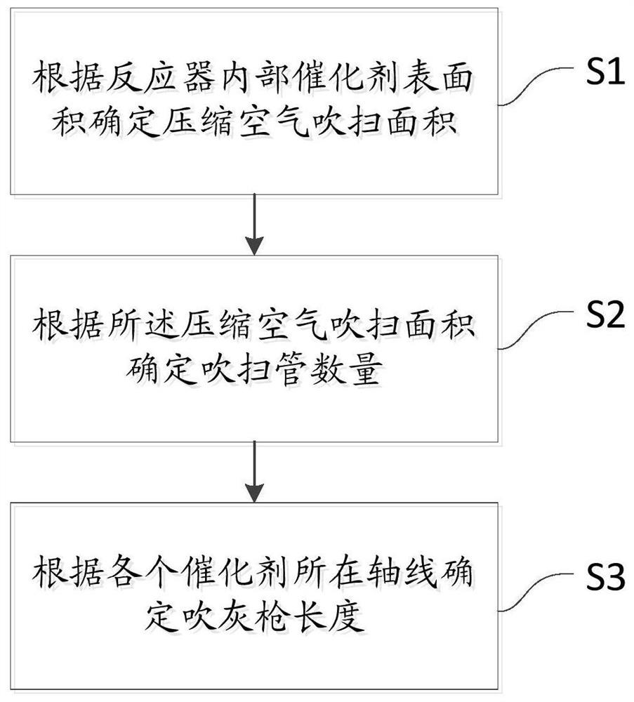
[0021] Please refer to figure 1 , figure 1 It is a flowchart of a specific embodiment provided by the present invention.

[0022] In a specific embodiment provided by the present invention, the above-mentioned SCR device soot blowing method includes:

[0023] Step 1: Determine the compressed air purge area according to the catalyst surface area inside the reactor;

[0024] Before dedusting the catalyst inside the reactor, it is necessary to calculate the su...


PUM


Abstract

The invention discloses an SCR device soot blowing method. The SCR device soot blowing method comprises the steps that the compressed air blowing area is determined according to the surface area of catalysts in a reactor; the number of blowing pipes is determined according to the compressed air blowing area; and the length of a soot blowing gun is determined according to the axis where the catalysts are located. According to the SCR device soot blowing method, the SCR soot blowing method is used for conducting dust removal on the surfaces of the catalysts in a system, compressed air is clean and transparent, fire catching is avoided, conveying is convenient, and the compressed air is inexhaustible; and secondly, the SCR soot blowing manner is used for achieving soot blowing without dead corners, blowing can be achieved for gaps between the catalysts, the compressed air serves as a soot blowing medium, equipment cannot be damaged, the running and maintaining cost is greatly reduced, andmeanwhile the soot blowing effect is guaranteed.

Description

technical field [0001] The invention relates to the technical field of metallurgy, in particular to a soot blowing method for an SCR device. Background technique [0002] The flue gas produced by the sintering plant in the production process of its metallurgical system contains a certain amount of NOx. Due to the large amount of dust attached to the flue gas, after long-term operation, the dust will adhere to the surface of the catalyst inside the denitrification device, resulting in a decline in the catalytic effect. [0003] In order to avoid the accumulation of dust, it is necessary to carry out soot blowing treatment in the reactor regularly to ensure the normal use of the catalyst inside the reactor. The general soot blowing treatment method is to use high-pressure steam to remove dust from the surface of the catalyst. Due to the temperature of high-pressure steam If it is higher, it will cause great damage to the main soot blowing gun. After long-term use, it is easy t...

Claims


Application Information

Patent Timeline
Patent Type & Authority Applications(China)
IPC IPC(8): B01D53/88B08B5/02B01D53/56
CPCB01D53/88B01D53/8625B08B5/02B01D2258/0283
Inventor 唐艳春郭小熠孙怀平秦保仁王正明
Owner SHANGHAI BAOYE GRP CORP
Learn More