Cooling device and method for fin type industrial magnetostrictive type ultrasonic transducer
A magnetostrictive and cooling device technology, applied in household refrigeration devices, applications, household appliances, etc., can solve the problem of affecting the long-term stable operation of ultrasonic transducers, restricting the industrial application and development of ultrasonic transducers, and increasing the number of production operators Work load and other issues, to achieve the effect of ensuring long-term stable operation, saving equipment installation costs and public works investment costs, and improving electro-acoustic conversion efficiency
- Summary
- Abstract
- Description
- Claims
- Application Information
AI Technical Summary
Problems solved by technology
Method used
Image

Examples
Embodiment 1
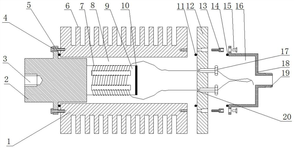
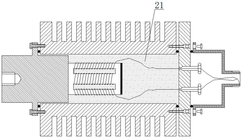
[0040] Such as Figure 1-2As shown, a finned industrial magnetostrictive ultrasonic transducer cooling device of the present invention includes a transducer cavity 8, a wiring cavity 16, a coil winding 7, a magnetostrictive material 9 and a vibrator block 2 , the coil winding 7, the whole of the magnetostrictive material 9 and a part of the vibrator block 2 are located inside the transducer cavity 8, and it is characterized in that: the transducer cavity shell 1 of the transducer cavity 8 is equipped with The fins 6 have a cylindrical structure, one end of which is equipped with a vibrator block 2, and the other end is equipped with an upper cover plate 12, and the remaining space inside is filled with quartz sand 21; the free end of the magnetostrictive material 9 is coated with a layer of sound-absorbing material 10.
[0041] The vibrator block 2 is provided with a connecting threaded hole 3 .
[0042] The vibrator block 2 is installed on one end of the transducer cavity s...
Embodiment 2
[0054] Such as Figure 1-2 As shown, the finned industrial magnetostrictive ultrasonic transducer cooling device is processed according to the following parameters, the transducer cavity shell 1 and the upper cover plate 12 are made of AL7075 aluminum alloy, and the outer diameter of the transducer cavity is The thickness of fins 6 is 5mm, the height is 15mm, the distance between adjacent fins 6 is 5mm, and the cooling area of fins is 0.23m 2 .
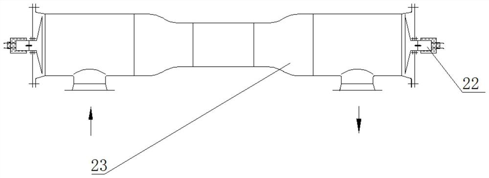
[0055] Such as Figure 3-4 As shown, the above-mentioned finned industrial magnetostrictive ultrasonic transducer cooling device is applied to a three-stage electric desalination tank with 8 million tons of ultrasonic waves to prevent oil sludge deposition in the electric desalination tank, and two sets of the present invention are installed in each ultrasonic wave action area pipeline Each electric desalination tank has 4 ultrasonic action area pipes. A total of 24 sets of cooling devices are installed in the three-stage electri...
Embodiment 3
[0062] Such as Figure 1-2 As shown, the finned industrial magnetostrictive ultrasonic transducer cooling device is processed according to the following parameters, the transducer cavity shell 1 and the upper cover plate 12 are made of AL7075 aluminum alloy, and the outer diameter of the transducer cavity is The thickness of fins 6 is 5mm, the height is 15mm, the distance between adjacent fins 6 is 5mm, and the cooling area of fins is 0.23m 2 .
[0063] Such as Figure 3-4 As shown, the above-mentioned finned industrial magnetostrictive ultrasonic transducer cooling device is applied to the secondary electric desalination tank application of 5 million tons of ultrasonic electric desalination and demulsification of a petrochemical company in a domestic tropical area, and a total of 8 sets of the present invention are used. The cooling device of the finned industrial magnetostrictive ultrasonic transducer replaces the cooling liquid cooling device disclosed in the original ...
PUM
 Abstract
Description
Claims
Application Information
 - R&D
- Intellectual Property
- Life Sciences
- Materials
- Tech Scout
- Unparalleled Data Quality
- Higher Quality Content
- 60% Fewer Hallucinations
Browse by: Latest US Patents, China's latest patents, Technical Efficacy Thesaurus, Application Domain, Technology Topic, Popular Technical Reports.
© 2025 PatSnap. All rights reserved.Legal|Privacy policy|Modern Slavery Act Transparency Statement|Sitemap|About US| Contact US: help@patsnap.com