Casting residual slag recovery and charging system

A charging system and powder slag technology are applied in the field of metallurgy to achieve the effects of eliminating costs, reducing dust, and reducing the number of workers

Pending Publication Date: 2020-11-24
GANSU JIU STEEL GRP HONGXING IRON & STEEL CO LTD
View PDF9 Cites 2 Cited by
  • Summary
  • Abstract
  • Description
  • Claims
  • Application Information

AI Technical Summary

Problems solved by technology

[0006] The purpose of the present invention is to provide a system for recovering and charging the remaining powder and slag, which solves the technical problem that there is no perfect technology that can effectively recycle the powder and slag

Method used


Image

  • Casting residual slag recovery and charging system
  • Casting residual slag recovery and charging system
  • Casting residual slag recovery and charging system

Examples


Embodiment 1

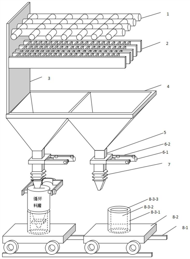
[0037] like figure 1 As shown, a system for recovering and charging the excess powder and slag of the present invention includes a frame and a primary fixed grid 1 for receiving and filtering the residual powder and slag, which is arranged inside the frame in turn, and is used to receive the primary fixed grid from the primary fixed grid. 1, the secondary active grid 2 for injecting and filtering the remaining powder slag, the powder collecting bin 4 for receiving the remaining powder slag from the secondary active grid 2, and the outlet port at the bottom of the access control powder collecting bin 4 The vertical pipe 5 and the valve 6 used for the on-off state of the vertical pipe 5, the movable feeder 7 installed at the output end of the vertical pipe 5 bottom and its own discharge port is retractable, and the movable feeder 7 arranged below the movable feeder 7 A charging assembly 8 for receiving materials from the movable feeder 7, and can be inserted into the charging ca...

Embodiment 2

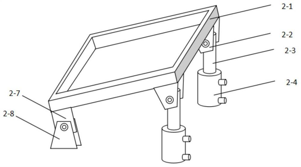
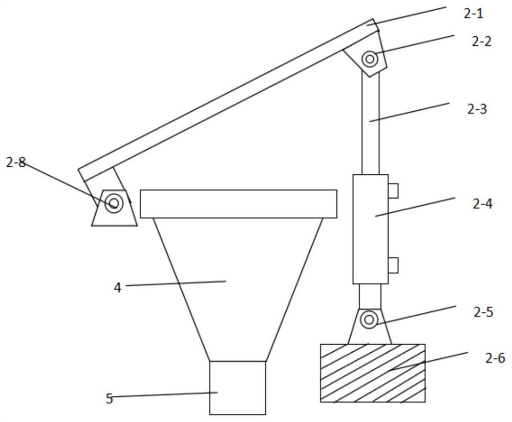
[0052] This embodiment is based on Embodiment 1, and describes the structure of the movable feeder.

[0053] like figure 1 , Figure 4 and Figure 5 As shown, in the present invention, the movable feeder 7 includes a wire rope winch fixed on the outer wall of the vertical pipe 5, a telescopic pipe 7-2-1 installed at the output end of the vertical pipe 5 bottom, and a telescopic pipe 7-2-1 fixed on the telescopic pipe 7- 2-1 is away from the plug-in charging nozzle 7-2-5 at one end of the vertical pipe 5, and the lifting end of the wire rope 7-1-7 of the wire rope winch is connected with the bottom of the telescopic pipe 7-2-1.

[0054] The telescopic tube 7-2-1 includes but is not limited to a telescopic bellows type high-strength fiber material tube.

[0055] Further, the lifting end of the steel wire rope 7-1-7 is connected to the bottom of the telescopic tube 7-2-1 through a connection assembly, and the connection assembly includes a lifting frame 7-2- 3. The wire rope ...


PUM


Abstract

The invention relates to the technical field of metallurgy, and particularly discloses a casting residual slag recovery and charging system. The casting residual slag recovery and charging system comprises a frame, and further comprises a primary fixed grid for receiving and filtering casting residual slag, a secondary movable grid for receiving and filtering the casting residual slag from the primary fixed grid, a slag collecting bin for receiving the casting residual slag from the secondary movable grid, a valve connected to a vertical pipe at the bottom outlet end of the slag collecting binand used for the on-off state of the vertical pipe, a movable feeder installed at the bottom output end of the vertical pipe and with a telescopic discharging port and a charging assembly arranged below the movable feeder and used for receiving materials from the movable feeder which are correspondingly and sequentially arranged on the inner side of the frame, and under the extension of the bottom discharging end of the movable feeder, the movable feeder can be inserted into a charging cavity of the charging assembly. According to the casting residual slag recovery and charging system, the difficult problem of recovery of the casting residual slag is effectively solved, and meanwhile the energy conservation and emission reduction and benefit improvement of enterprises can further be promoted.

Description

technical field [0001] The invention relates to the technical field of metallurgy, in particular to a system for recovering and charging excess powder slag. Background technique [0002] The remaining top slag poured into the ladle after refining in the steelmaking process is equivalent to a kind of refining slag premixed in the steelmaking process. It has high alkalinity, good metallurgical properties, reasonable composition, and fast slag melting. Except for some furnaces with high S content, the S in the slag of most furnaces is not saturated, and it can be reused in the refining process for the second or even third use to save lime, save auxiliary materials such as slag fluorite, and increase slag Quantity, promote slagging, improve submerged arc, protect ladle refractory, save power consumption and shorten refining cycle, so as to promote the cost reduction and efficiency increase of enterprises. [0003] At present, many iron and steel enterprises equipped with refini...

Claims


Application Information

Patent Timeline
Patent Type & Authority Applications(China)
IPC IPC(8): B09B5/00B07B1/46
CPCB09B5/00B07B1/46B07B1/4609B07B2201/04
Inventor 陈亚团魏国立朱青德
Owner GANSU JIU STEEL GRP HONGXING IRON & STEEL CO LTD
Why Eureka
Try Eureka