Gear grinding machine

A gear grinding machine and internal gear technology, which is applied in the field of gear grinding machines, can solve the problems of operation site use and large overall size of the gear grinding machine, and achieve the effect of reducing floor space, compact structure and reducing overall size.

Inactive Publication Date: 2020-11-24
HENAN UNIV OF SCI & TECH
View PDF10 Cites 3 Cited by
  • Summary
  • Abstract
  • Description
  • Claims
  • Application Information

AI Technical Summary

Problems solved by technology

[0005] The purpose of the present invention is to provide a gear grinding machine capable of processing both external gears and internal gears, so as to solve the technical problem that the overall size of the gear grinding machine in the prior art is large and it is difficult to use it in a small work site

Method used


Image

  • Gear grinding machine
  • Gear grinding machine
  • Gear grinding machine

Examples


specific Embodiment 1

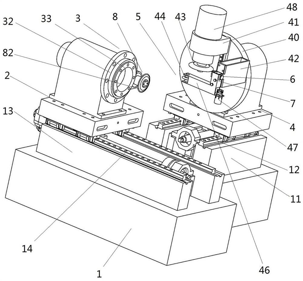
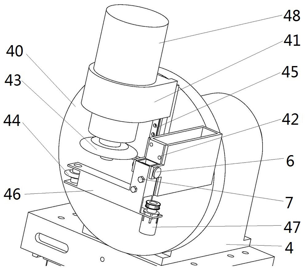
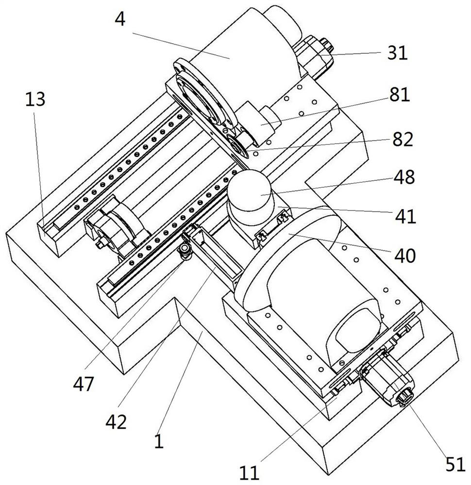
[0051] like figure 1 , image 3 and Figure 5 As shown, the gear grinding machine includes a base 1, a workpiece mechanism slide 2, a workpiece mechanism 3, a grinding wheel mechanism slide 5, and a grinding wheel mechanism 4. The workpiece mechanism slide 2 is guided and slidably installed on the base 1 along the front and rear directions, and the workpiece mechanism 3 is installed on the slide table 2 of the workpiece mechanism; the slide table 5 of the grinding wheel mechanism is guided and slid on the base 1 along the left and right directions, and the grinding wheel mechanism 4 is installed on the slide table 5 of the grinding wheel mechanism. The workpiece mechanism 3 is used for installing the workpiece to be processed, and the grinding wheel mechanism 4 is used for installing the grinding wheel for grinding the workpiece to be processed.

[0052] Specifically, the front and rear directions correspond to the X direction, the left and right directions correspond to the...

specific Embodiment 2

[0067]The main difference between it and the above-mentioned embodiment 1 is that in the above-mentioned embodiment 1, the external tooth mounting seat is in the working position or the avoidance position by sliding up and down. In this embodiment, the external gear mounting base is hinged to the grinding wheel turret, and the hinge shaft extends along the front and rear directions. At this time, the external gear mounting base is in the working position or the avoidance position by swinging.

specific Embodiment 3

[0069] The difference between it and the above-mentioned embodiment 1 mainly lies in that in the above-mentioned embodiment 1, the internal tooth mounting seat is in the working position or the avoidance position by swinging. In this embodiment, the inner tooth swing arm is guided and slid up and down and installed on the grinding wheel turntable, and the inner tooth mounting seat is in the working position or the avoidance position by swinging.


PUM


Abstract

The invention relates to a gear grinding machine. The gear grinding machine comprises a base, a workpiece mechanism and a grinding wheel mechanism are mounted on the base, the grinding wheel mechanismcomprises a grinding wheel mounting base, an external tooth mounting seat and an internal tooth mounting seat, wherein the external tooth mounting seat is used for mounting an external tooth grindingwheel so as to grind an external gear, the internal tooth mounting seat is used for mounting an internal tooth grinding wheel so as to grind an internal gear, the external tooth mounting seat is movably mounted on the grinding wheel mounting base, a working position and an avoiding position are arranged on the moving stroke of the external tooth mounting seat, the internal tooth mounting seat ismovably mounted on the grinding wheel mounting base, a working position and an avoiding position are arranged on the moving stroke of the internal tooth mounting seat, when the external gear is ground, the external tooth mounting seat is in the working position, and the internal tooth mounting seat is in the avoiding position, so that the external gear is normally ground through the external toothgrinding wheel; and when the internal gear is ground, the internal tooth mounting seat is in the working position, and the external tooth mounting seat is in the avoiding position, so that the internal gear is normally ground through the internal tooth grinding wheel, and the utilization rate of the gear grinding machine is improved.

Description

technical field [0001] The invention relates to a gear grinding machine. Background technique [0002] With the development of the manufacturing industry and the wide application of robots, the requirements for machining accuracy of gears are getting higher and higher. Therefore, the demand for gear grinding machines is increasing. Existing gear grinding machine, such as the gear grinding machine disclosed by the invention patent of CN101433983B with the authorized announcement number, the gear grinding machine comprises: bed, column, bed saddle, grinding wheel headstock, workpiece headstock and numerical control system, and the bed is equipped with The linear guide rails are 90° each other, the column is installed on one of the linear guide rails, the bed saddle is installed on the other linear guide rail, the grinding wheel headstock is installed on the column, and the grinding wheel headstock constitutes the grinding wheel mechanism of the gear grinding machine; the bed s...

Claims


Application Information

Patent Timeline
IPC IPC(8): B23F5/02B23F23/00
CPCB23F5/02B23F23/00
Inventor 苏建新李晨刘光宗吴培鑫程琛
Owner HENAN UNIV OF SCI & TECH
Why Eureka
Try Eureka