Thermocouple welding device
A welding device and thermocouple technology, applied in welding equipment, welding accessories, arc welding equipment, etc., can solve the problems of high cost of welding equipment and complicated operation, and achieve the effect of eliminating pollution, simple principle, fast and efficient welding
- Summary
- Abstract
- Description
- Claims
- Application Information
AI Technical Summary
Problems solved by technology
Method used
Image


Examples
Embodiment Construction
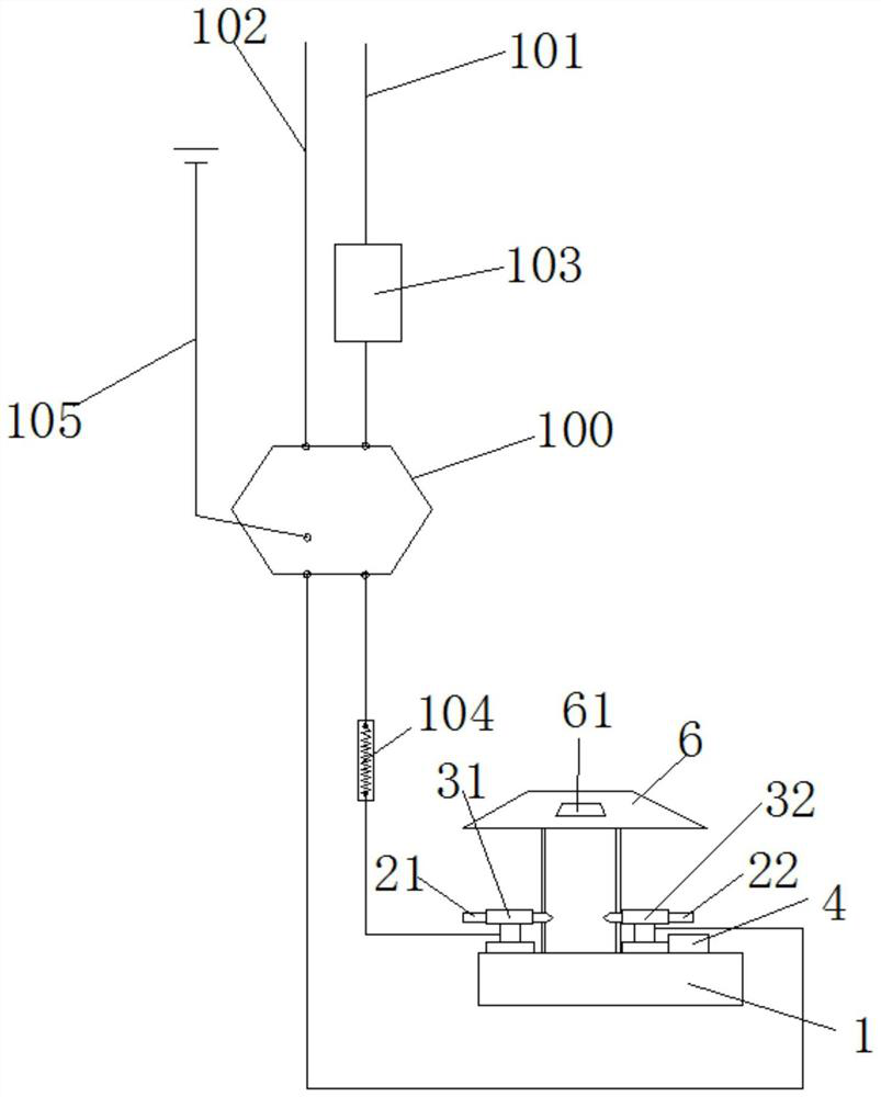
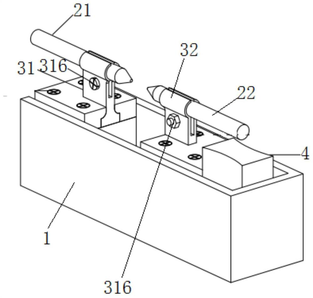
[0022] see in conjunction Figure 1 to Figure 6 As shown, according to an embodiment of the present invention, a thermocouple welding device is provided, including a welding part and a power supply circuit, wherein the welding part includes a device base 1, and the device base 1 is provided with a first carbon rod 21, The second carbon rod 22, the tip of the first carbon rod 21 and the tip of the second carbon rod 22 are spaced apart from each other in the axial direction, and the first carbon rod 21 and the second carbon rod 22 are respectively connected in series In the power supply line, when the power supply line is in the power supply state, an arc can be formed in the gap between the tip of the first carbon rod 21 and the tip of the second carbon rod 22 . In this technical solution, the first carbon rod 21 and the second carbon rod 22 are respectively connected in series in the power supply line, so that the first carbon rod 21 and the second carbon rod 22 can An electr...
PUM
 Abstract
Description
Claims
Application Information
 - Generate Ideas
- Intellectual Property
- Life Sciences
- Materials
- Tech Scout
- Unparalleled Data Quality
- Higher Quality Content
- 60% Fewer Hallucinations
Browse by: Latest US Patents, China's latest patents, Technical Efficacy Thesaurus, Application Domain, Technology Topic, Popular Technical Reports.
© 2025 PatSnap. All rights reserved.Legal|Privacy policy|Modern Slavery Act Transparency Statement|Sitemap|About US| Contact US: help@patsnap.com