
Intelligent operation room shifting device

A technology for shifting devices and operating rooms, which is applied to workbenches, manipulators, and program-controlled manipulators. It can solve problems such as unstable liquid states, potential safety hazards, and difficulty in maintaining a stable internal liquid state, achieving good protection and proper movement. Effect

Pending Publication Date: 2020-11-24
浙江华地电子有限公司
View PDF5 Cites 0 Cited by
  • Summary
  • Abstract
  • Description
  • Claims
  • Application Information

AI Technical Summary

Problems solved by technology

[0003] Therefore, whether it is using the mechanical arm to cooperate with the mechanical structure for industrial manufacturing or object handling, it is necessary to assemble a displacement device to achieve the corresponding action. Among the existing various displacement devices, when the mechanical components cooperate to achieve During the operation, among the objects loaded, especially the objects carrying liquid, it is difficult to maintain the stability of the internal liquid state when moving, especially when transporting liquid chemicals, the unstable liquid state is likely to bury safety hazards

Method used


Image

  • Intelligent operation room shifting device
  • Intelligent operation room shifting device
  • Intelligent operation room shifting device

Examples


Embodiment 1

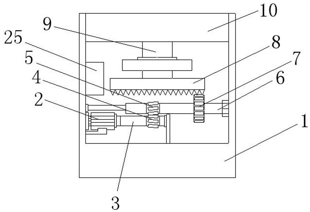
[0030] Embodiment 1, according to Figure 1-2 , the second controller 25 sends out a signal, and the second controller 25 controls the action of the first motor 2. With the rotation of the output end of the first motor 2, the driving rod 3 is driven to rotate, and the gap between the first gear 4 and the second gear 5 is used to The meshing effect to drive the rotating rod 6 to rotate, and then drive the third gear 7 to rotate through the rotating rod 6, and through the meshing effect between the third gear 7 and the ring gear 8, drive the ring gear 8 to rotate, and let the ring gear 8 The connecting column 9 drives the turntable 10 to rotate to realize the angle adjustment action of the whole device.

Embodiment 2

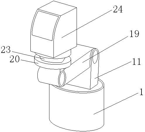
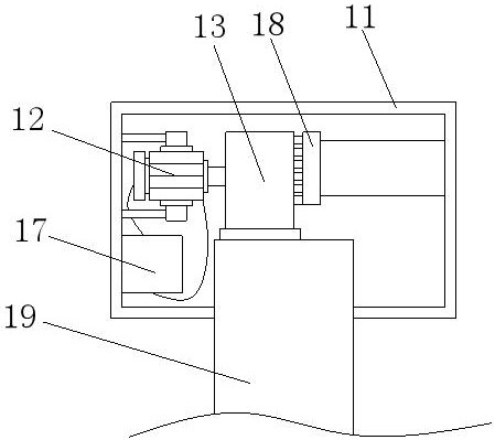
[0031] Embodiment 2, according to figure 1 , Figure 3-5 , Figure 8 , when adjusting the position of the console 24, the second motor 12 is controlled by the first controller 17 to operate, and the steering wheel 13 is driven to rotate with the rotation of the output end of the second motor 12. When the steering wheel 13 rotates, the limit The block 16 escapes from the groove provided inside the fixed block 18 by the compression spring 15. After the steering wheel 13 stops rotating, the limiting block 16 enters the groove inside the fixed block 18 again under the action of the spring 15, and controls the steering The angle of the tray 13 is fixed so that the height of the console 24 can be changed.

Embodiment 3

[0032] Embodiment 3, according to Figure 6-7 , when the overall device rotates and the height of the console 24 lifts, the electromagnet 22 is energized and generates magnetism at the end in contact with the magnetic plate 21, which strengthens the magnetic force of the magnetic plate 21, and the magnetic force produced by the magnetic plate 21 and the magnetic ball 23 The magnetic force between them keeps the operating table 24 in a suspended state all the time, and keeps the center of gravity of the operating table 24 at one point all the time, thereby realizing the maintenance of the stable state of the operating table 24.

[0033] Working principle: when in use, when the overall device needs to be rotated, the external control device sends a signal to the second controller 25, and the second controller 25 controls the action of the first motor 2, and through the rotation of the output end of the first motor 2, Drive the driving rod 3 to rotate, and then drive the rotating...


PUM


Abstract

The invention discloses an intelligent operation room shifting device. The intelligent operation room shifting device comprises a base, wherein a first motor is fixedly installed in the base, a driving rod is fixedly installed at the output end of the first motor, a first gear is fixedly installed on the outer surface of the driving rod, a second gear is engaged with the first gear, a rotating rodpenetrates through the center of the second gear, a third gear is fixedly installed on the outer surface of the rotating rod, and a gear ring is engaged with the third gear. According to the intelligent operation room shifting device, a signal sent by a second controller is matched with the matching between the driving rod, the rotating rod and the gear ring, the horizontal angle adjustment of the whole device is achieved, an internal device of a positioning column is matched to achieve the lifting of an operation table, and meanwhile when the operation table is rotated and lifted, through the magnetic force between a magnetic plate and a magnetic ball, in the form of magnetic suspension, it is guaranteed that the operation table can maintain good stability no matter in any movement state.

Description

technical field [0001] The invention relates to the technical field of intelligent control, in particular to an intelligent operating room shifting device. Background technique [0002] The robotic arm refers to a complex system with high precision, multiple input and multiple output, high nonlinearity, and strong coupling. Because of its unique operational flexibility, it has been widely used in industrial assembly, safety and explosion-proof fields. The robotic arm is a complex system. There are uncertainties such as parameter perturbation, external interference, and unmodeled dynamics, so the modeling model of the manipulator also has uncertainty. For different tasks, it is necessary to plan the motion trajectory of the joint space of the manipulator to cascade Form the end pose. [0003] Therefore, whether it is using the mechanical arm to cooperate with the mechanical structure for industrial manufacturing or object handling, it is necessary to assemble a displacement ...

Claims


Application Information

Patent Timeline
IPC IPC(8): B25H1/14B25H1/16B25J9/12
CPCB25H1/14B25H1/16B25J9/126B25J9/102
Inventor 平庆义郭连坤
Owner 浙江华地电子有限公司
Learn More