
Vent valve for closed tank

A technology of exhaust valve and airtight box, applied in the direction of ventilation valve, exhaust device, exhaust device, etc., can solve problems such as loss of sealing function of rubber seals, reduce internal pressure, prevent overflow, reduce manufacturing cost effect

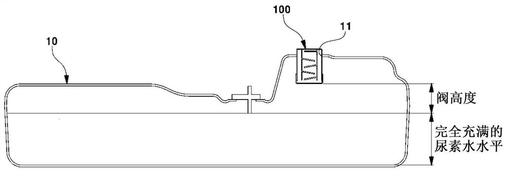
Pending Publication Date: 2020-11-24
HYUNDAI MOTOR CO LTD +1
View PDF0 Cites 0 Cited by
  • Summary
  • Abstract
  • Description
  • Claims
  • Application Information

AI Technical Summary

Problems solved by technology

Therefore, when the conventional spring valve is applied to the urea water tank, white powder remains in the rubber seal part provided to prevent liquid leakage, causing a problem of loss of the sealing function of the rubber seal

Method used


Image

  • Vent valve for closed tank
  • Vent valve for closed tank
  • Vent valve for closed tank

Examples


Embodiment Construction

[0026] Reference will now be made in detail to various embodiments of the invention, examples of which are illustrated in the accompanying drawings and described below. While the invention will be described in conjunction with exemplary embodiments thereof, it will be understood that present description is not intended to limit the invention to those exemplary embodiments. On the other hand, the present invention is intended to cover not only the exemplary embodiments of the present invention, but also various alternatives, modifications, equivalents and other implementations, which may be included within the spirit and scope of the present invention as defined by the appended claims. example.

[0027] Hereinafter, various exemplary embodiments of the present invention will be described in detail with reference to the accompanying drawings so that the present invention can be easily implemented by those of ordinary skill in the art to which the present invention pertains.

[...


PUM


Abstract

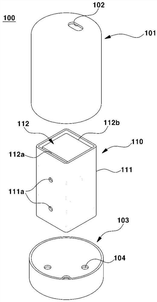
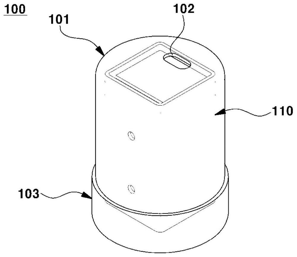
The present invention relates to a vent valve for a closed tank. The vent valve is provided in an upper surface of the closed tank for storing liquid, may include an upper housing provided with an upper air hole disposed outside the closed tank; a lower housing provided with a lower air hole disposed inside the closed tank; and a valve core provided in a housing space area surrounded by the upperhousing and the lower housing and providing a ventilation path through which only gas passes between the upper air hole and the lower air hole.

Description

technical field [0001] The present invention relates generally to an exhaust valve for an airtight box, and more particularly, to an air exhaust valve for an airtight box that can ensure desired air permeability of an airtight box. Background technique [0002] Diesel engine vehicles utilize urea water systems to clean their exhaust. The urea water system supplies urea water to a catalytic converter of an engine exhaust system, and the urea water supplied to the catalytic converter reacts with NOx in exhaust gas to reduce NOx into nitrogen and water. [0003] The urea water system is provided with a urea water tank for storing urea water. The urea water tank is provided with an exhaust valve in order to relieve the positive pressure generated in the urea water tank when the urea water evaporates in the urea water tank, and relieve the negative pressure generated in the urea water tank when the urea water is discharged from the urea water tank. [0004] As a conventional ex...

Claims


Application Information

Patent Timeline
Patent Type & Authority Applications(China)
IPC IPC(8): F16K24/04
CPCF16K24/04F01N2610/1466F01N2610/02F01N3/2066F01N13/18Y02A50/20Y02T10/12B60K15/03519B60K2015/03256B60K2015/03368B60K2015/03309B65D51/1644B65D81/263B65D2205/02
Inventor 崔承训朴埈莹林埈植李泰允李性元
Owner HYUNDAI MOTOR CO LTD
Learn More