
Biomass particle burner capable of improving burning rate

A biomass particle and burner technology, which is applied in the combustion method, combustion equipment, solid fuel combustion and other directions, can solve the problems of clogging the furnace, unexpected shutdown, furnace damage, etc., to improve combustion efficiency, facilitate cleaning, and prevent coking. Effect

Pending Publication Date: 2020-11-24
徐守文
View PDF19 Cites 2 Cited by
  • Summary
  • Abstract
  • Description
  • Claims
  • Application Information

AI Technical Summary

Problems solved by technology

[0003] The existing biomass pellet burners still have the following deficiencies in actual use: First, because the traditional biomass pellet burners all use screw feeders for feeding, and the burner needs to enter at least about one-fifth of the The ignition work can only be carried out with a certain amount of fuel, which will lead to the accumulation of combustion particles at the bottom of the combustion furnace, resulting in insufficient combustion, and the used biomass pellet fuel contains oil, sugar, and a small amount of minerals in the wood and straw materials. During the combustion process, it will be severely coked, forming slag blockage, blocking the furnace, and causing the biomass burner to fail to operate normally; secondly, after the biomass particles are coked, the grate will be blocked, affecting the air supply, and the heat will accumulate due to the coke blocks blocking the grate At the grate position, the higher the temperature, the easier it is to coke. If it is not treated, it will cause flameout and unexpected production stoppage. Therefore, it is necessary to open the grate opening to clean the furnace after a period of time, because the coke blocks are glued to the furnace after cooling. , it is difficult to clean, and it is easy to cause damage to the furnace body

Method used


Image

  • Biomass particle burner capable of improving burning rate
  • Biomass particle burner capable of improving burning rate
  • Biomass particle burner capable of improving burning rate

Examples


Embodiment Construction

[0021] The following will clearly and completely describe the technical solutions in the embodiments of the present invention with reference to the accompanying drawings in the embodiments of the present invention. Obviously, the described embodiments are only some, not all, embodiments of the present invention. Based on the embodiments of the present invention, all other embodiments obtained by persons of ordinary skill in the art without making creative efforts belong to the protection scope of the present invention.

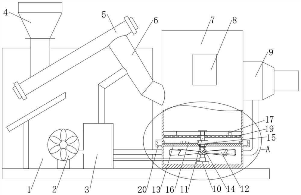
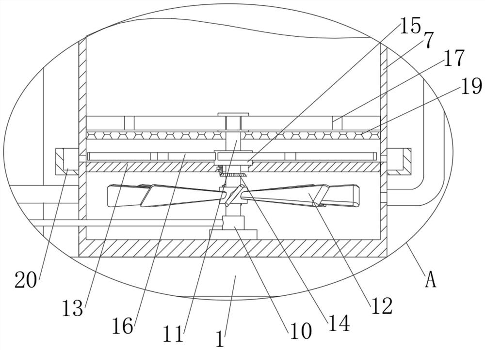
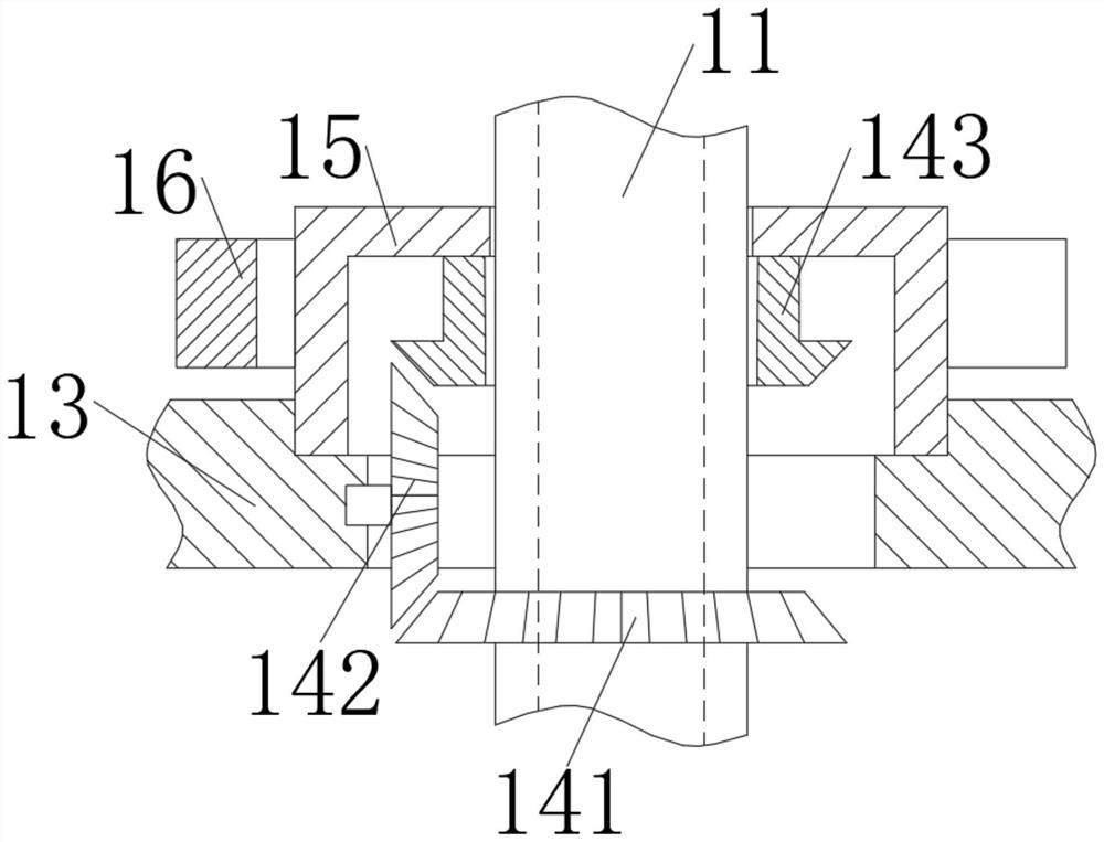
[0022] see Figure 1-7 , a biomass particle burner for increasing the combustion rate, comprising a device main body 1, a fan 2, an air box 3, and a combustion furnace 7 are sequentially installed on the bottom of the device main body 1, and a feed hopper 4 is fixedly installed on the upper part of the device main body 1, The bottom of the feeding hopper 4 is fixedly connected with a feeding screw 5, the bottom of one end of the feeding screw 5 is fixedly conn...


PUM


Abstract

The invention relates to the technical field of burning equipment, and discloses a biomass particle burner capable of improving the burning rate. The biomass particle burner comprises an equipment body, wherein a fan, an air box and a burning furnace are sequentially installed at the bottom of the equipment body; a feeding hopper is fixedly installed on the upper portion of the equipment body; anda feeding screw is fixedly connected to the bottom of the feeding hopper. Through the arrangement of a cleaning plate and an air supply device, air rushing to fan blades from the air box drives the cleaning plate to rotate, burning ash above a metal filter screen is smashed, the purpose of smashing the burning ash before coking is achieved, and coking is prevented; the air passing through a rotary joint and a hollow shaft enters an air supply channel, a wedge block is jacked open under the air pressure for ventilation, the smashed ash is blown to a fire spraying opening through wind power forsecondary burning, and coking is prevented while the burning efficiency is improved; and the wedge block is in a closed state under the action of a spring under the non-ventilation condition, and thesituation that burning particles, impurities and the like enter the air supply channel, and consequently the air supply channel is blocked is avoided.

Description

technical field [0001] The invention relates to the technical field of combustion equipment, in particular to a biomass particle burner with improved combustion rate. Background technique [0002] The burner is a high-efficiency and energy-saving biomass combustion equipment developed mainly for industrial furnaces, coating, drying, die-casting and other industries. This series of products uses biomass particles as fuel and adopts semi-gasification composite combustion technology. It has a reasonable structure and is fully automatic. Intelligent control. At present, the burners used in the market are mainly screw-type feeding methods. The fuel in the hopper is transported to the combustion chamber through the screw for full combustion. [0003] The existing biomass pellet burners still have the following deficiencies in actual use: First, because the traditional biomass pellet burners all use screw feeders for feeding, and the burner needs to enter at least about one-fifth o...

Claims


Application Information

Patent Timeline
IPC IPC(8): F23B70/00F23L5/02
CPCF23B70/00F23L5/02
Inventor 徐守文
Owner 徐守文
Learn More