
Method for heating solution containing HCFO-1233zd(E) in absorber

An absorber and heat-absorbing technology, applied in sorption machines, heat pumps, refrigerators, etc., can solve problems such as poor heat transfer temperature difference matching, high pressure requirements for heat exchange equipment, and lower pressure requirements for equipment to achieve stable performance. , the effect of excellent thermodynamic performance and reduced manufacturing cost

Pending Publication Date: 2020-11-24
浙大宁波理工学院
View PDF11 Cites 0 Cited by
  • Summary
  • Abstract
  • Description
  • Claims
  • Application Information

AI Technical Summary

Problems solved by technology

[0007] In order to solve the problem of poor matching between the heat transfer temperature difference between the system and the heat transfer medium and the high pressure requirements for the heat exchange equipment, the present invention proposes a , 3-trifluoropropene) solution heating method in the absorber, using the absorber and desorber to replace the condenser and evaporator in the traditional vapor compression refrigeration system, and preferably the solution containing HCFO-1233zd (E) in the absorption Variable temperature heat release and heat absorption occur in the desorber and desorber to achieve a better match between the heat transfer temperature difference between the system and the heat transfer medium; at the same time, due to the presence of the absorbent, the absorption pressure or desorption pressure is much lower than that at the same temperature Condensing pressure or evaporation pressure, thus reducing the pressure requirements on the equipment

Method used


Image

  • Method for heating solution containing HCFO-1233zd(E) in absorber
  • Method for heating solution containing HCFO-1233zd(E) in absorber
  • Method for heating solution containing HCFO-1233zd(E) in absorber

Examples


Embodiment 1

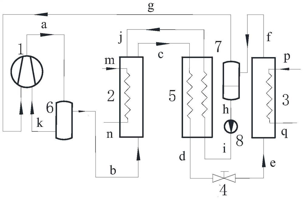
[0033] Such as figure 1 As shown, in the system described in this embodiment, the air outlet of the compressor 1 is connected to the air inlet of the oil separator 6, the air outlet of the oil separator 6 is connected to the air inlet of the absorber 2, and the solution outlet of the absorber 2 is connected to the air inlet of the absorber 2. The first inlet of the solution heat exchanger 5 is connected, the first outlet of the solution heat exchanger 5 is connected with the solution inlet of the desorber 3 through the expansion device 4, the solution outlet of the desorber 3 is connected with the inlet of the gas-liquid separator 7, and the gas-liquid The gas outlet of the separator 7 is connected with the air inlet of the compressor 1, the liquid outlet of the gas-liquid separator 7 is connected with the second inlet of the solution heat exchanger 5, and the second outlet of the solution heat exchanger 5 is connected with the absorber 2 The solution inlet is connected.

[0...

Embodiment 2

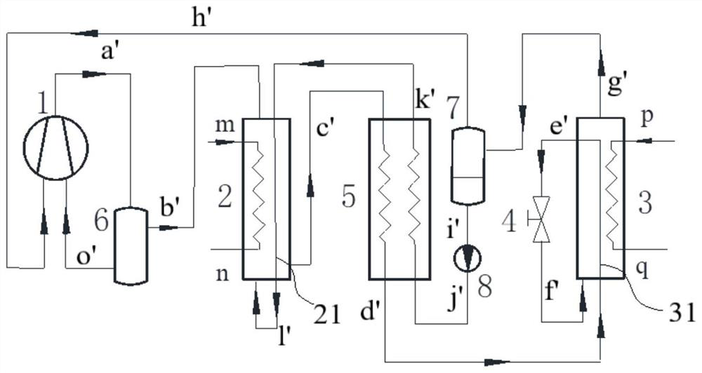
[0037] Such as figure 2 As shown, the difference between this embodiment and Embodiment 1 is that a superheated pipeline 21 is provided in the absorber 2 , and a supercooled pipeline 31 is provided in the desorber 3 . The workflow is as follows:

[0038] The mixture a' containing HCFO-1233zd(E) and lubricating oil at the outlet of compressor 1 enters the oil separator 6, and the lubricating oil separated by the oil separator 6 passes through the liquid outlet and is decompressed into o' to return to the compressor, so The steam b' containing HCFO-1233zd(E) at the gas outlet of the oil separator 6 enters the absorber 2; the outlet of the solution heat exchanger 5 can absorb the absorbent k' of HCFO-1233zd(E) first in the absorber 2 Preheated to l', and then enter the absorber 2, in the absorber 2, the steam b' is absorbed by the absorbent l', release heat of absorption, and at the same time the heat transfer medium or refrigerant in the absorber 2 Or the subject m to be heat...

Embodiment 3

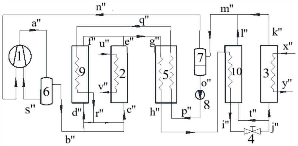
[0041] Such as image 3 As shown, the difference between this embodiment and Embodiment 1 is that it also includes a superheater 9 and a subcooler 10, the superheater 9 is arranged between the oil separator 6 and the heat absorber 2, and the subcooler 10 is arranged between the desorption Between device 3 and gas-liquid separator 7. The workflow is as follows:

[0042] The mixture a" containing HCFO-1233zd(E) and lubricating oil at the outlet of compressor 1 enters the oil separator 6, and the lubricating oil separated by the oil separator 6 passes through the liquid outlet and is decompressed into s" and returns to the compressor. The steam b" containing HCFO-1233zd(E) at the gas outlet of the oil separator 6 is divided into two parts, one part enters the absorber 2, and in the absorber 2, HCFO-1233zd(E) can be absorbed from the outlet of the superheater 9 The absorbent r" absorbs and releases the heat of absorption. At the same time, the heat transfer medium or refrigerant...


PUM


Abstract

The invention discloses a method for heating a solution containing HCFO-1233zd(E) in an absorber. The method comprises the steps of absorbing vapor containing HCFO-1233zd(E) in the absorber, and releasing absorption heat. According to the method, a condenser and an evaporator in a traditional vapor compression refrigeration system are replaced by the absorber and a desorber, and additionally, thesolution containing HCFO-1233zd(E) is selected to release heat at variable temperature and absorbing heat at variable temperature in the absorber and the desorber, so that the system is preferably matched with the heat transfer temperature difference of a heat transfer medium; an absorbent exists, the absorbing pressure or desorption pressure are respectively far lower than the condensing pressureor evaporating pressure at the same temperature, so that the pressure bearing requirement of equipment is reduced.

Description

technical field [0001] The invention relates to a method for heating a solution containing HCFO-1233zd(E) (trans-1-chloro-3,3,3-trifluoropropene) in an absorber. Background technique [0002] Nature contains a large amount of low-temperature heat energy, such as geothermal energy, solar energy, etc. In addition, human production processes will also produce a large amount of low-temperature heat, such as petrochemical, metallurgical building materials, food processing, etc., such as low-temperature waste heat. Direct discharge will not only pollute The environment will also cause energy waste. At the same time, in the industrial production process, there is a high demand for heat sources with a temperature of 80°C or higher. Therefore, using waste heat recovery technology to obtain heat from low-temperature heat sources to produce high-temperature heat has important environmental protection and economic benefits. It is also a new development direction in my country's energy fie...

Claims


Application Information

Patent Timeline
Patent Type & Authority Applications(China)
IPC IPC(8): F25B30/04F25B15/02F25B43/00F25B43/02F25B41/06
CPCF25B15/02F25B30/04F25B43/00F25B43/02Y02B30/62Y02A30/27
Inventor 宣永梅陈光明高能吴勇平
Owner 浙大宁波理工学院
Learn More