
Centrifugal micro-fluidic chip electrochemical detection device and method

A microfluidic chip and detection method technology, applied in the field of electrochemical detection, can solve the problems of inability to perform automatic detection, need for manual cleaning, and low work efficiency, and achieve the effect of reducing human intervention, reducing manual input, and simple structure

Inactive Publication Date: 2020-11-24
周小丽
View PDF0 Cites 2 Cited by
  • Summary
  • Abstract
  • Description
  • Claims
  • Application Information

AI Technical Summary

Problems solved by technology

[0003] At present, microfluidic chips have been widely used in the field of electrochemical detection, but the existing electrochemical detection devices can only detect a small amount of samples during detection, the operation is cumbersome, and automatic detection cannot be performed, and manual cleaning is required after the detection is completed. Complicated operation and low work efficiency
[0004] Through the above analysis, the problems and defects of the existing technology are: the existing electrochemical detection device can only detect a small amount of samples during detection, the operation is cumbersome, and automatic detection cannot be performed, and manual cleaning is required after the detection is completed. Complicated and inefficient

Method used


Image

  • Centrifugal micro-fluidic chip electrochemical detection device and method
  • Centrifugal micro-fluidic chip electrochemical detection device and method
  • Centrifugal micro-fluidic chip electrochemical detection device and method

Examples


Embodiment Construction

[0057] In order to make the object, technical solution and advantages of the present invention more clear, the present invention will be further described in detail below in conjunction with the examples. It should be understood that the specific embodiments described here are only used to explain the present invention, not to limit the present invention.

[0058] Aiming at the problems existing in the prior art, the present invention provides a centrifugal microfluidic chip electrochemical detection device and method. The present invention will be described in detail below with reference to the accompanying drawings.

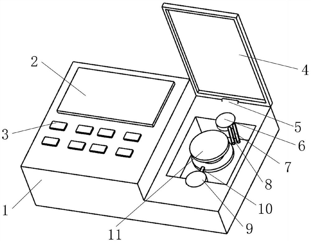
[0059] Such as figure 1 As shown, the left side of the shell 1 is the control area, the display screen 2 is arranged above the control area, and the control button 3 is set below the display screen 2; the right side of the shell 1 is the detection area, and the top of the detection area is connected to the detection area cover through the rotating shaft 4. An ...


PUM


Abstract

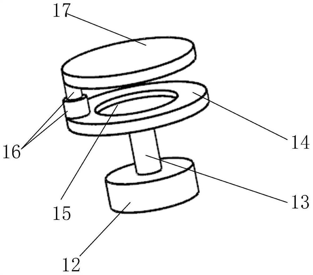
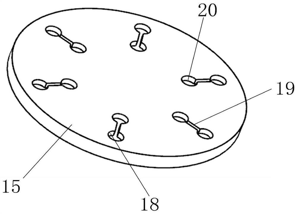
The invention belongs to the technical field of electrochemical detection, and discloses a centrifugal micro-fluidic chip electrochemical detection device and method. A control area is arranged on theleft side of a shell, a display screen is arranged above the control area, and control buttons are arranged below the display screen. A detection area outer cover is connected to the top of the detection area through a rotating shaft, an electrochemical detection area is arranged in the middle of the detection area, and a first rotating table and a second rotating table are arranged at the frontend and the rear end of the electrochemical detection area respectively. A pretreatment tank is sequentially arranged above the micro-fluidic chip in the circumferential direction and is connected with a detection tank through a micro-channel. The device is simple in structure, the single-chip microcomputer control system is adopted to achieve automatic control over the whole detection process, data export and cleaning, the automation degree is high, human intervention is reduced, the detection result is more accurate, and the detection efficiency is improved.

Description

technical field [0001] The invention belongs to the technical field of electrochemical detection, in particular to a centrifugal microfluidic chip electrochemical detection device and method. Background technique [0002] At present, the microfluidic chip is the hot spot in the development of the current micro-analysis system. The microfluidic chip analysis uses the chip as the operating platform, is based on analytical chemistry, relies on micro-electromechanical processing technology, takes the micro-pipeline network as the structural feature, and takes life science as the current main application object. It is the current micro-total analysis system field. focus of development. Its goal is to integrate the functions of the entire laboratory, including sampling, dilution, reagent addition, reaction, separation, detection, etc., on the microchip, and it can be used multiple times. [0003] At present, microfluidic chips have been widely used in the field of electrochemica...

Claims


Application Information

Patent Timeline
Patent Type & Authority Applications(China)
IPC IPC(8): G01N27/26B01L3/00G06K9/62
CPCG01N27/26B01L3/502753B01L3/5027B01L2200/10G06F18/2431G06F18/25
Inventor 周小丽韩建林朱事康邵秋荣
Owner 周小丽
Learn More