
ldmos device and its manufacturing method

A manufacturing method and device technology, applied in semiconductor/solid-state device manufacturing, semiconductor devices, electrical components, etc., can solve problems such as reducing device production efficiency and increasing device manufacturing costs, achieving uniform depletion layer distribution and improving withstand voltage performance. , the effect of reducing the base resistance

Active Publication Date: 2022-07-15
JOULWATT TECH INC LTD
View PDF6 Cites 0 Cited by
  • Summary
  • Abstract
  • Description
  • Claims
  • Application Information

AI Technical Summary

Problems solved by technology

[0004] In the traditional process, in order to improve the electrical characteristics and self-protection ability of the LDMOS device, it is necessary to add an additional mask (mask) or use other more complicated processes during fabrication, thereby increasing the manufacturing cost of the device and reducing the production of the device efficiency

Method used


Image

  • ldmos device and its manufacturing method
  • ldmos device and its manufacturing method
  • ldmos device and its manufacturing method

Examples


Embodiment Construction

[0036] The present invention will be described in more detail below with reference to the accompanying drawings. In the various figures, like elements are designated by like reference numerals. For the sake of clarity, various parts in the figures have not been drawn to scale. Additionally, some well-known parts may not be shown. For the sake of simplicity, the semiconductor structure obtained after several steps can be depicted in one figure.

[0037] It will be understood that, in describing the structure of a device, when a layer or region is referred to as being "on" or "over" another layer or region, it can be directly on the other layer or region, or Other layers or regions are also included between it and another layer, another region. And, if the device is turned over, the layer, one region, will be "under" or "under" another layer, another region.

[0038] In order to describe the situation directly above another layer or another area, expressions such as "directl...


PUM


Abstract

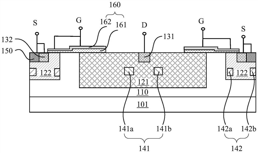
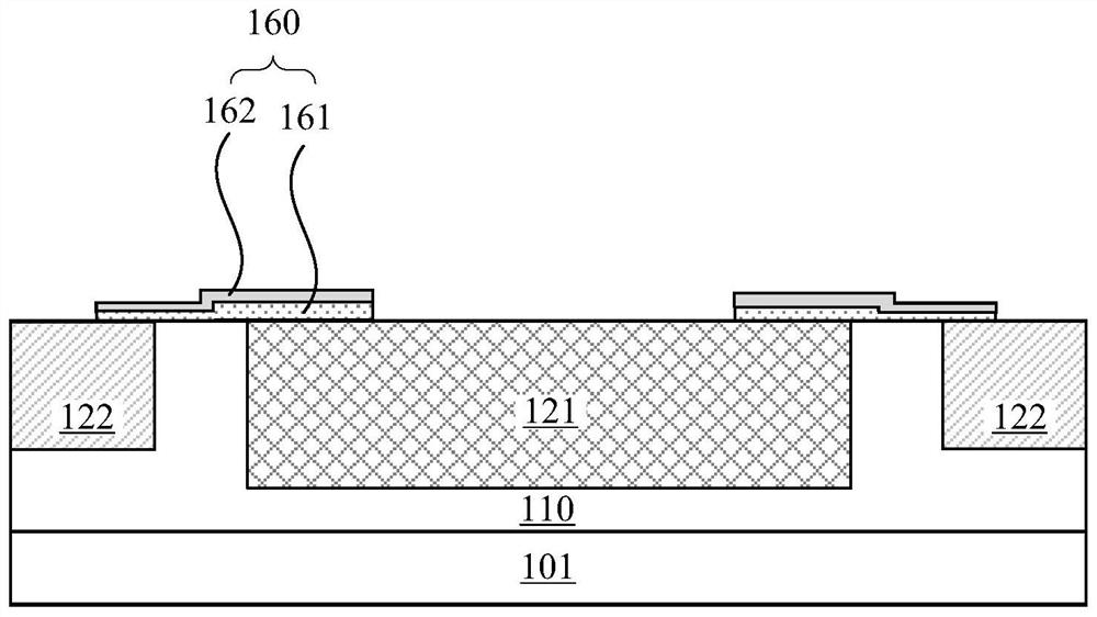
This patent application discloses an LDMOS device and a manufacturing method thereof. The manufacturing method includes: forming an epitaxial layer over a substrate, implanting a drift region and a well region in the epitaxial layer; forming a gate structure over part of the well region; A first mask with a first opening is formed above the epitaxial layer, and an inversion region is formed by implanting at an oblique angle of the first opening. The inversion region is doped opposite to the drain region in the drift region and is symmetrical about the drain region. At the same time, An additional doping region of the same doping type as the well region is formed in the well region through the second opening of the first mask; then the source region and the drain region are also doped in the first opening and the second opening. The advantage of this patent is that the same mask is used to form the drain region, the inversion region in the drift region, and the additional doping region in the well region with the same doping concentration as the well region, which can not only effectively increase the breakdown voltage of the device, but also reduce the The on-resistance of the device is improved, and the self-protection capability of the device is improved without adding any additional cost.

Description

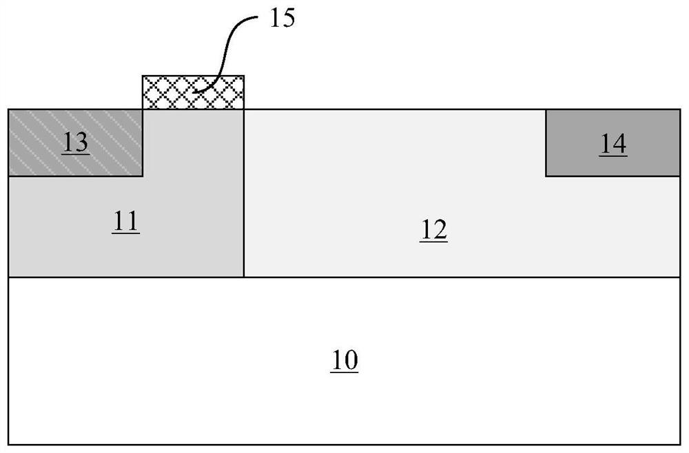
technical field [0001] The present application relates to the field of semiconductor device manufacturing, and more particularly, to an LDMOS device and a manufacturing method thereof. Background technique [0002] Laterally-diffused metal-oxide semiconductor (LDMOS) devices can meet the requirements of high voltage resistance and power control, and are often used in radio frequency power circuits. like figure 1 As shown, the LDMOS device includes: a substrate 10, a well region 11 and a drift region 12 located on the substrate 10 and in contact with each other, a source region 13 located in the well region 11, a drain region 14 located in the drift region 12, and a source region 14 located in the drift region 12. Gate structure 15 on well region 11 . Taking an N-type LDMOS device as an example, the substrate 10 and the well region 11 are P-type doped, and the drift region 12 , the source region 13 and the drain region 14 are all N-type doped. In the LDMOS device, the well...

Claims


Application Information

Patent Timeline
Patent Type & Authority Patents(China)
IPC IPC(8): H01L29/78H01L21/336H01L29/06
CPCH01L29/7816H01L29/66681H01L29/0603H01L29/0615
Inventor 葛薇薇
Owner JOULWATT TECH INC LTD
Learn More