Gas-phase packed bed discharge plasma generating device

A technology for discharging plasma and generating device, applied in the direction of plasma, electrical components, etc., can solve the problems of affecting the discharge situation, lack of discharge, affecting the effect of material modification, etc., and achieve the effect of real-time spectral detection and uniform degradation treatment

Inactive Publication Date: 2020-11-24
DALIAN UNIV OF TECH
View PDF8 Cites 4 Cited by
  • Summary
  • Abstract
  • Description
  • Claims
  • Application Information

AI Technical Summary

Problems solved by technology

When modifying the surface of the material, in some current technologies, the material to be modified is usually placed directly on the lower insulating dielectric plate, and the modification is carried out in the atmospheric environment, ignoring the fixation of the material in the discharge area, resulting in modification To deal with the phenomenon of inhomogeneity, and the current dielectric barrier discharge is deficient in the discharge of various gas environments, the existing technology is to directly connect the ventilation pipe between the insulating dielectric plates, and the flow rate of the air flow in the insulating dielectric plates is not uniform, and then Affect the discharge condition and affect the modification effect of the material

Method used


Image

  • Gas-phase packed bed discharge plasma generating device
  • Gas-phase packed bed discharge plasma generating device
  • Gas-phase packed bed discharge plasma generating device

Examples


Embodiment 1

[0028] Example 1: Oxygen plasma modified adsorption resin XAD-2

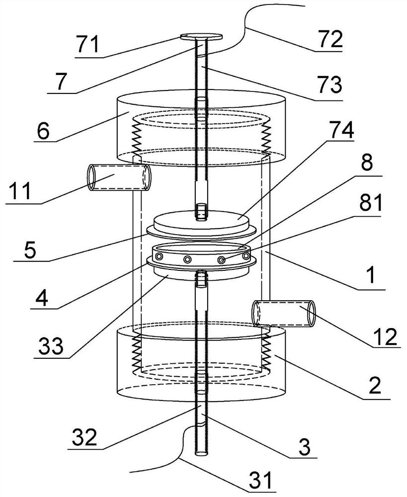
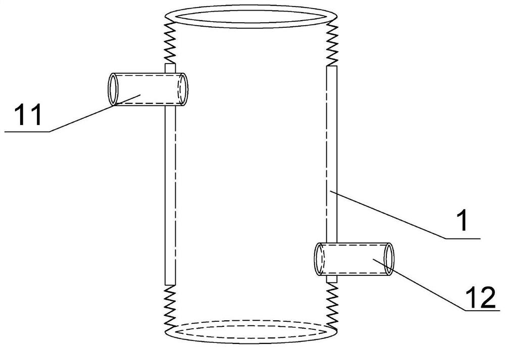
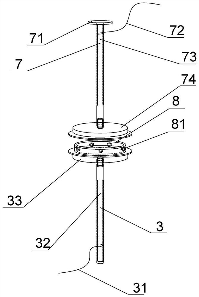
[0029] In the present embodiment, the plasma reactor housing 1 has a diameter of 14 cm and a height of 20 cm. The shape of the packed bed 8 is circular with air holes and a height of 3 mm. The diameter of the air holes 81 is 1.5 mm. The high-voltage electrode plate 74 and the low-pressure The electrode plates 33 are all stainless steel circular plates with a diameter of 8 cm and a thickness of 3 cm. The lower insulating dielectric plate 4 and the upper insulating dielectric plate 5 are ceramic sheets with a thickness of 0.5 mm. The amount of XAD-2 resin to be treated is 2 g . Oxygen is used as the discharge gas. Discharge parameters: the discharge voltage is 28kV, the frequency is 120Hz, the discharge time is 2-40min, and the intermittent time is 2min. The XAD-2 resin modified at each time point is tested for naphthalene adsorption performance, and the test result is: the adsorption performance of XAD-2 adsorp...

Embodiment 2

[0030] Embodiment 2: nitrogen plasma degrades trimethoprim solution

[0031] In this embodiment, the packed bed 8 is a square quartz glass tank with an inner diameter of 100*100, the packed bed height is 5 cm, the high-voltage electrode plate 74 is an array needle electrode, and the distance between every two needle electrodes is 6 mm. 33 is a plate electrode, and the lower insulating dielectric plate 4 and the upper insulating dielectric plate 5 are ceramic sheets with a thickness of 0.5mm. Operating parameters: the discharge voltage is 30kV, the discharge frequency is 120Hz, nitrogen is the discharge gas, and the trimethoprim solution is tested after 10 minutes of discharge treatment. The test result is: the degradation efficiency of trimethoprim can reach 89.5%.


PUM


Abstract

The invention provides a gas-phase packed bed discharge plasma generating device, which comprises a plasma reactor shell body, a lower sealing end cover, an upper sealing end cover, a low-voltage electrode structure, a high-voltage electrode structure and a packed bed, wherein the upper and lower sealing end covers are connected to the upper and lower parts of the plasma reactor shell body; the upper sealing end cover is connected with a high-voltage electrode structure, and the lower sealing end cover is connected with a low-voltage electrode structure; the high-voltage electrode structure comprises a high-voltage screw rod, a high-voltage electrode plate, an adjusting hand wheel, a high-voltage power line and an upper insulating dielectric plate; the low-voltage electrode structure comprises a grounding power line, a low-voltage screw rod, a low-voltage electrode plate and a lower insulating dielectric plate; and the packed bed is fixed on the upper surface of the lower insulating dielectric plate. The gas-phase packed bed discharge plasma generating device disclosed by the invention can realize dielectric barrier discharge of different gas components, is convenient for observinga discharge phenomenon, can measure a spectrum in real time, realizes surface modification experiments of materials such as an adsorbent and the like, and realizes degradation experiments of liquid-phase pollutants in different gas environments.

Description

technical field [0001] The invention belongs to the field of experimental equipment, and in particular relates to a gas phase packed bed discharge plasma generating device. Background technique [0002] Dielectric barrier discharge has a simple structure, is easy to operate, and can generate large-area plasma regions and abundant active species. It is widely used in pollutant degradation and material surface modification, that is, samples to be treated are placed in the discharge gap. When modifying the surface of the material, in some current technologies, the material to be modified is usually placed directly on the lower insulating dielectric plate, and the modification is carried out in the atmospheric environment, ignoring the fixation of the material in the discharge area, resulting in modification To deal with the phenomenon of inhomogeneity, and the current dielectric barrier discharge is deficient in the discharge of various gas environments, the existing technology...

Claims


Application Information

Patent Timeline
Patent Type & Authority Applications(China)
IPC IPC(8): H05H1/24
CPCH05H1/2406
Inventor 徐庆南杨德正王红丽周雄峰
Owner DALIAN UNIV OF TECH
Why Eureka
Try Eureka