Induction heating device

An induction heating device and sensor technology, applied in the direction of tobacco, etc., can solve the difficulty in controlling the consistency of the solder joint size, the consistency of the solder joint pulling force, and the difficulty in controlling the consistency of the heating effect of the wound coil, which affects the popularization and use of heating appliances. and other problems, to achieve the effect of accurate and convenient temperature detection, high electromagnetic conversion efficiency and saving structural space

Pending Publication Date: 2020-11-27
HUIZHOU KIMREE TECH
View PDF0 Cites 3 Cited by
  • Summary
  • Abstract
  • Description
  • Claims
  • Application Information

AI Technical Summary

Problems solved by technology

However, since the induction heating device supplies the induction coil with high-frequency alternating current through the power supply and the control unit to generate an alternating magnetic field, so that the metal susceptor can induce heat energy, the winding process of the traditional induction coil is complicated, and it is difficult to control the consistency of the coil heating effect. sex
Moreover, the volume of the coil after winding is relatively large, which affects the popularization and use of heating appliances
[0003] In order to accurately control the thermal energy generated by the heating body to produce a consistent mist, it is necessary to monitor the temperature on the surface of the heating body at any time. Most of the existing temperature monitoring methods are to touch and weld thermocouple wires on the surface of the heating body to achieve the surface temperature of the heating body Monitoring, it is difficult to control the size consistency of solder joints and the consistency of the pull-out force of solder joints during touch welding, and the welding wire on the middle surface of the heating body brings difficulties to the sealing of the entire heating module, which affects the consistency and cost of the device

Method used


Image

  • Induction heating device
  • Induction heating device
  • Induction heating device

Examples


Embodiment Construction

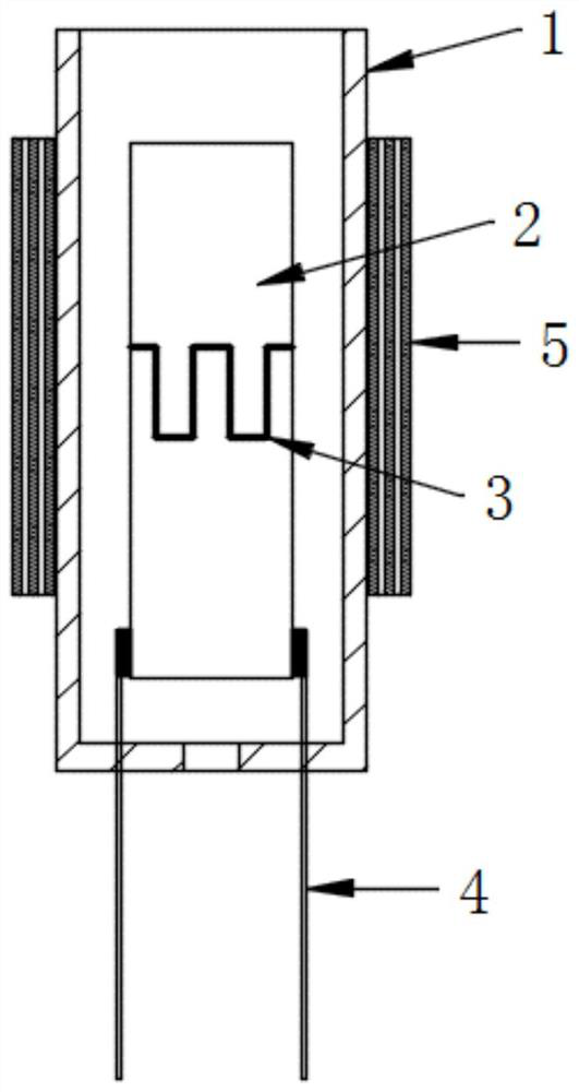
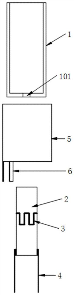
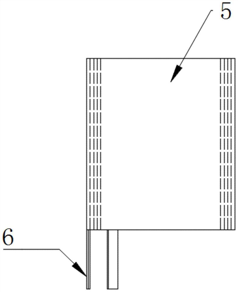
[0037] In order to solve the problems of low energy conversion efficiency of the induction coil of the induction heating device in the prior art, difficulty in winding the coil, and poor consistency of the heating effect after winding; It is difficult to control the size consistency of the solder joints and the consistency of the pull-out force of the solder joints during touch welding, and the welding wire on the middle surface of the heating body brings difficulties to the sealing of the entire heating module, which affects the consistency and cost of the device. The present invention aims to provide an induction heating device, the core idea of ​​which is: an inductor is formed by wrapping a metal sheet around the outer surface of an insulating tube several times. Compared with ordinary coils, the inductor has a simpler winding process and is easy to control Consistency of the heating effect, its effective cross-section is larger, so the electromagnetic conversion efficiency...


PUM


Abstract

The invention provides an induction heating device, which comprises a device shell, a power supply and a control unit, and is characterized in that the device shell comprises a cavity for accommodating at least one part of an aerosol generating substance, a heating base body arranged in the cavity, and an inductor capable of generating a magnetic field axis; the control unit is connected to the inductor and is configured to provide high-frequency alternating current for the inductor; the inductor is a metal sheet with high conductivity, and the metal sheet is arranged to surround at least onepart of the outer surface of the cavity to form at least one layer of winding. The inductor is larger in effective cross section and better in electromagnetic conversion efficiency, the temperature measurement circuit is printed on the heating base body, temperature detection of the heating base body is more accurate and convenient, the manufacturing process is mature and simple, consistency is excellent, and the defects of butt welding of thermocouple wires on the surface of a heating body in the prior art are overcome.

Description

technical field [0001] The invention relates to the technical field of low temperature smoke, in particular to an induction heating device. Background technique [0002] Such as Figure 14 As shown, in the current low-temperature smoke popular on the market, the induction heating device used to heat the aerosol-generating substance overcomes some problems existing in the ceramic heating substrate, such as the temperature field The uniformity of the heating matrix is ​​better, and the molding consistency of the heated substrate is better. However, since the induction heating device supplies the induction coil with high-frequency alternating current through the power supply and the control unit to generate an alternating magnetic field, so that the metal susceptor can induce heat energy, the winding process of the traditional induction coil is complicated, and it is difficult to control the consistency of the coil heating effect. sex. Moreover, the volume of the coil after w...

Claims


Application Information

Patent Timeline
Patent Type & Authority Applications(China)
IPC IPC(8): A24F40/465A24F40/40A24F40/50A24F40/70
CPCA24F40/40A24F40/465A24F40/50A24F40/70
Inventor 陈盛军郝刚肖金红陈伟洪
Owner HUIZHOU KIMREE TECH
Why Eureka
Try Eureka