
Hot-blast stove combustor rapid cleaning method and tool

A cleaning method and burner technology, applied in furnaces, blast furnaces, heating furnaces, etc., can solve the problems of difficult pouring of refractory materials, difficult to clean up completely, poor stability of effects, etc., and achieve the improvement of technical indicators and the time required for cleaning. Short, obvious effect of wind temperature rise

Active Publication Date: 2020-11-27
SGIS SONGSHAN CO LTD
View PDF6 Cites 2 Cited by
  • Summary
  • Abstract
  • Description
  • Claims
  • Application Information

AI Technical Summary

Problems solved by technology

The manhole above the burner of the temporary shutdown hot blast stove is opened at least above 1000°C. In the case of high time-limited requirements, it is difficult to clean thoroughly without special tools
The existing treatment method is: cut the steel shell of the hot blast furnace under the manhole according to the position of the vertical ruler on the surface of the burner, open a new hole, and clean the bricks with the vertical ruler. After cleaning, the steel shell is welded, and the internal refractory material is castable Filling recovery, but due to the high internal temperature of the burner, the refractory pouring operation is difficult, and the effect stability is poor, resulting in high temperature and redness around the newly opened hole when the blast furnace is blowing air, which poses a safety risk

Method used


Image

  • Hot-blast stove combustor rapid cleaning method and tool
  • Hot-blast stove combustor rapid cleaning method and tool
  • Hot-blast stove combustor rapid cleaning method and tool

Examples


Embodiment Construction

[0029] The present invention will be described in detail below in conjunction with the accompanying drawings and embodiments.

[0030] It is worth noting that the orientation words such as "up" and "down" involved in this article are all determined relative to the perspective of the drawings, and are only for the convenience of description, and cannot be understood as limitations on the technical solution.

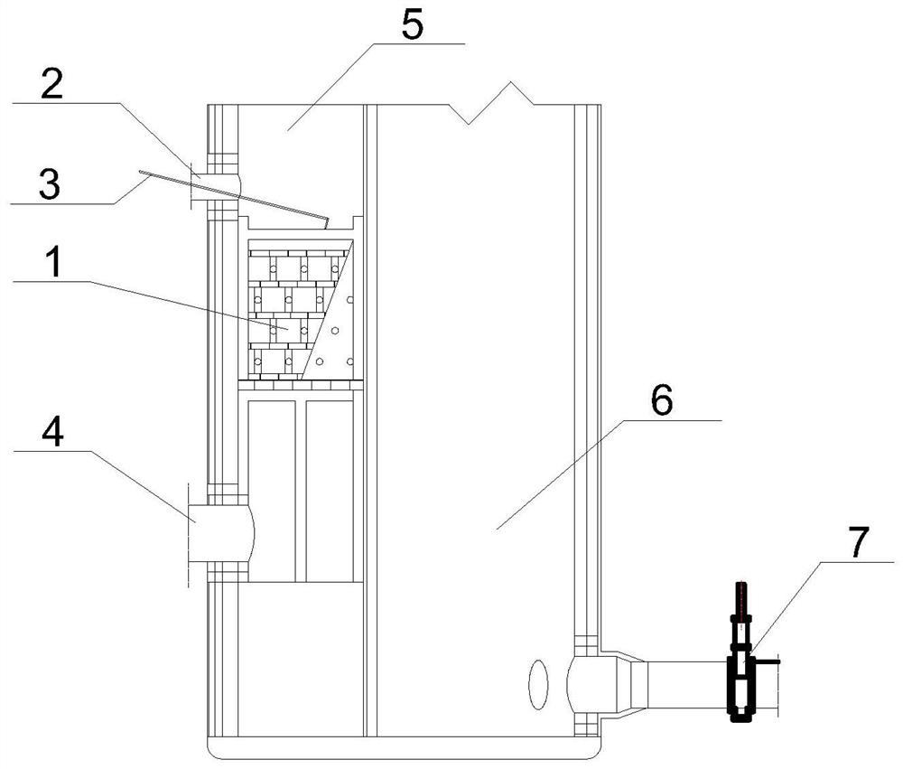
[0031] Such as Figure 1-5 As shown, a quick cleaning method and tool for a hot blast stove burner, comprising the following steps:

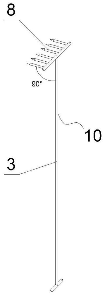
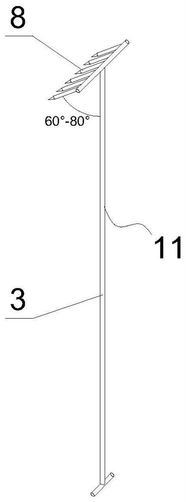
[0032] S1, make cleaning tool, cleaning tool comprises the first comb rake 10, the second comb rake 11 and the first plate rake 12, the second plate rake 13: the first comb rake 10 and the second comb rake 11 are all made of straight bar 3 and Composed of the first rake body 8, the first rake body 8 is comb-shaped, the difference is that the straight bar 3 of the first comb rake 10 is perpendicular to the first rake body 8, and the straight...


PUM


Abstract

The invention relates to a hot-blast stove combustor rapid cleaning method and tool. The method comprises the following steps that the cleaning tool is manufactured, and comprises a comb rake and a plate rake; after damping-down operation of a blast furnace is accomplished, all valves of the hot-blast stove are closed according to the stove stuffiness requirements, a backflow valve is opened and kept in a full-open state; after the coal is driven by a coal gas system, a steel shell located outside an ignition hole and a refractory material located inside the ignition hole are taken down; refractory bricks located on the top of a combustor are cleaned by the cleaning tool until grid holes of the combustor are cleaned; an inspection manhole formed in the bottom of the combustor is taken down, the inspection manhole is located between an air and gas branch pipe of the hot-blast stove and the combustor, and the cleaning tool enters the interior from the inspection manhole to clean a channel of the air and gas branch pipe; and after cleaning is completed, the refractory material inside the ignition hole is blocked according to an original design drawing, and the outer steel shell and the inspection manhole are reassembled. According to the hot-blast stove combustor rapid cleaning method and tool, the required cleaning time is short, the method can be synchronously carried out duringthe regular repair of the blast furnace, the combustor cleaning effect is good, the air temperature rise is obvious, and the potential safety hazards caused by coal gas segregation can be eliminated.

Description

technical field [0001] The invention relates to the technical field of blast furnace hot blast stove technology, more specifically, it relates to a method and tool for quick cleaning of a hot blast stove burner. Background technique [0002] The burner of the internal combustion hot blast stove is at the bottom of the fire well. After the collapse of bricks above the fire well, all of them will fall into the burner area. Large refractory bricks are piled on the surface of the burner, and small refractory bricks will fall into the burner from top to bottom The air and gas passages below. As a result, the grid holes above the burner and the air and gas passages below are blocked. When the hot blast stove is fired, the amount of gas burned is greatly reduced, and the heat storage of the regenerator and the temperature of the air sent out are also greatly reduced. At the same time, because the grid holes above the burner are unevenly blocked, the gas that can pass through the r...

Claims


Application Information

Patent Timeline
IPC IPC(8): C21B9/10C21B9/04
CPCC21B9/10C21B9/04
Inventor 杨国新艾中路沈志宏李伟庄锦填潘伟恩柏徳春陈炯张志坚
Owner SGIS SONGSHAN CO LTD
Features
  • Generate Ideas
  • Intellectual Property
  • Life Sciences
  • Materials
  • Tech Scout
  • Unparalleled Data Quality
  • Higher Quality Content
  • 60% Fewer Hallucinations
Learn More