Multi-cutter-disk heading machine

A roadheader and multi-cutter technology, which is applied to mining equipment, earthwork drilling, tunnels, etc., can solve problems such as unsatisfactory excavation of large-section tunnels, expand the scope of geological application, improve operating efficiency, and improve excavation efficiency and the effect of the effect

Active Publication Date: 2020-11-27
CHINA RAILWAY ENGINEERING EQUIPMENT GROUP CO LTD
View PDF11 Cites 8 Cited by
  • Summary
  • Abstract
  • Description
  • Claims
  • Application Information

AI Technical Summary

Problems solved by technology

[0006] In view of the deficiencies in the above-mentioned background technology, the present invention proposes a multi-cutter heading machine, which solves the technical problem that the existing road heading machine cannot meet the excavation requirements of large-section tunnels.

Method used


Image

  • Multi-cutter-disk heading machine
  • Multi-cutter-disk heading machine
  • Multi-cutter-disk heading machine

Examples


Embodiment 1

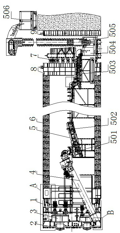
[0052] Embodiment 1, a kind of multi-cutter heading machine, such as figure 1 As shown, it includes an outer shell 1 that plays a supporting role. The front end of the outer shell 1 is provided with a drive system 3 connected to an excavation mechanism 2. The excavation mechanism 2 is equipped with a slag discharge system 4 and a slag conveying system 5 . The rear part of the outer shell 1 is provided with a jacking system 7, and the jacking system 7 cooperates with the outer shell 1 through the top iron 8 and the pipe joint 6 in sequence. Under the pushing action of the jacking system 7, the excavation mechanism 2 realizes the excavation of the face, and the excavated muck is transported to the muck conveying system 5 through the slag discharging system 4, and then conveyed by the muck conveying system 5. Drain the muck.

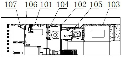
[0053] Specifically, such as figure 2 As shown, the outer casing 1 includes a front casing 101, a middle casing 102 and a rear casing 103 connected in ...

Embodiment 2

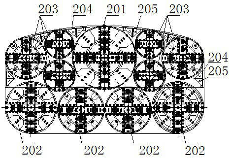
[0065] Embodiment 2, a kind of multi-cutter heading machine, such as Figure 7 As shown, the large cutterhead 201 and the medium cutterhead 202 are spoke-and-plate cutterheads, and the spoke-and-plate cutterhead includes radially arranged spokes and a faceplate. The small cutterhead 203 is a spoked cutterhead, and the spoked cutterhead includes radially arranged spokes.

[0066] Described large-scale cutterhead 201, medium-sized cutterhead 202, small-sized cutterhead 203 all comprise the big ring 206 that is arranged on outer beam outer end, and the circumferential direction of big ring 206 and described panel are all arranged with tearing knife 207, big circle The tearing knives on ring 206 act as gauge knives. A hob 208 and a scraper 209 are arranged on the spokes, and a central fishtail knife 210 is arranged at the centers of the large cutterhead 201 , the medium cutterhead 202 and the small cutterhead 203 .

[0067] Further, as Figure 8 As shown, a stirring rod 211 is ...


PUM


Abstract

The invention discloses a multi-cutter-disk heading machine which comprises an outer shell. A drive system is arranged at the front end of the outer shell and is connected with an excavation mechanism; the excavation mechanism is provided with a deslagging system and a muck conveying system; the excavation mechanism comprises a plurality of cutter disks; the multiple cutter disks are arranged at the front end of the outer shell in parallel; the orthographic projections of the cutter disks form a shape consistent to the cross section of the outer shell; a gap between each two adjacent cutter disks and a gap between each cutter disk and the outer shell are excavation blind areas; a blind area conical plate is arranged at the position, opposite to each excavation blind area, on the outer shell; the deslagging system comprises a blind area screw conveyer; a rock breaking structure opposite to each excavation blind area is arranged at the front end of the blind area screw conveyer; and theblind area screw conveyer is connected with the muck conveying system. The multi-cutter-disk heading machine provided by the invention not only can achieve the maximum effects of excavation and stirring, but also plays a role in supporting a palm surface to prevent collapse. Meanwhile, the geological application scope of the extra-large rectangular section heading equipment over 14 meters is expanded.

Description

technical field [0001] The invention belongs to the technical field of tunnel excavation in sand and pebble layers, in particular to a multi-cutter heading machine. Background technique [0002] With the continuous acceleration of the urbanization process, in the urban underground space construction projects, underground underground excavation mechanical construction has become a trend. Among them, the rectangular tunnel boring machine is used more and more because of its advantages of high space utilization, suitable for shallow covering soil, relatively low construction cost and less impact on the surrounding environment. At present, rectangular tunnel boring machines are mainly used for the construction of subway entrances and exits, street passages, double-lane underpass highways, sidewalks, and comprehensive pipe corridors, but the equipment used is all rectangular sections below 10 meters. [0003] At present, the tunnel section is developing towards a larger and wide...

Claims


Application Information

Patent Timeline
Patent Type & Authority Applications(China)
IPC IPC(8): E21D9/11E21D9/12E21D9/10
CPCE21D9/11E21D9/12E21D9/124E21D9/1093
Inventor 蒋鹏鹏龚廷民徐德帆孙英杰万国伟陈家浩袁征
Owner CHINA RAILWAY ENGINEERING EQUIPMENT GROUP CO LTD
Why Eureka
Try Eureka