Optical imaging system, image capturing module and electronic device

An optical imaging system and optical axis technology, applied in optics, optical components, instruments, etc., can solve the problems that the resolution cannot meet the needs of consumers, the size of the imaging module increases, and achieve smooth light at the edge of the field of view, The effect of reducing breakage and facilitating stability

Pending Publication Date: 2020-11-27
JIANGXI JINGCHAO OPTICAL CO LTD
View PDF0 Cites 10 Cited by
  • Summary
  • Abstract
  • Description
  • Claims
  • Application Information

AI Technical Summary

Problems solved by technology

At present, the five-chip imaging module is widely used in the market, but its resolution is increasingly unable to meet the needs of consumers. Compared with the five-chip imaging module, the seven-chip imaging module can obtain higher resolution, and can be used in mobile electronic products, thereby improving the image quality, resolution and clarity of shooting. In addition, the performance of photosensitive elements such as photocoupler (CCD) and complementary metal oxide semiconductor (CMOS) also has certain advantages. It has greatly improved, provided the possibility to shoot high-quality picture quality, and brought people a higher-quality shooting experience
[0003] In the process of implementing this application, the inventor found that there are at least the following problems in the prior art: due to the small volume of mobile electronic products, the volume of the imaging module will also increase with the increase in the number of lenses. It is difficult for the slice imaging module to achieve high imaging quality while achieving miniaturization

Method used


Image

  • Optical imaging system, image capturing module and electronic device
  • Optical imaging system, image capturing module and electronic device
  • Optical imaging system, image capturing module and electronic device

Examples


no. 1 example

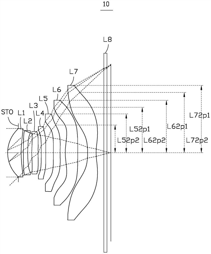
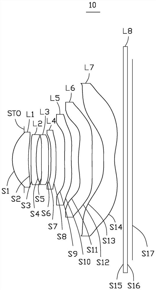
[0133] Please refer to figure 2 and image 3 , the optical imaging system 10 of the first embodiment includes a diaphragm STO, a first lens L1 with positive refractive power, a second lens L2 with negative refractive power, and a third lens with positive refractive power from the object side to the image side L3, fourth lens L4 with negative refractive power, fifth lens L5 with negative refractive power, sixth lens L6 with positive refractive power, seventh lens L7 with negative refractive power, and infrared filter L8.

[0134] Wherein, the near optical axis of the object side S1 of the first lens L1 is a convex surface, and the near optical axis of the image side S2 is a concave surface; the second lens L2 has a convex surface at the near optical axis of the object side S3, and the near optical axis of the image side S4 is Concave surface; the object side S5 near optical axis of the third lens L3 is convex, and the image side S6 near optical axis is convex; the object side...

no. 2 example

[0143] Please refer to Figure 4 and Figure 5 , the optical imaging system 20 of the second embodiment includes a stop STO, a first lens L1 with a positive refractive power, a second lens L2 with a negative refractive power, and a third lens with a negative refractive power from the object side to the image side. L3, fourth lens L4 with positive refractive power, fifth lens L5 with negative refractive power, sixth lens L6 with positive refractive power, seventh lens L7 with negative refractive power, and infrared filter L8.

[0144] Wherein, the near optical axis of the object side S1 of the first lens L1 is a convex surface, and the near optical axis of the image side S2 is a concave surface; the second lens L2 has a convex surface at the near optical axis of the object side S3, and the near optical axis of the image side S4 is Concave surface; the object side S5 near optical axis of the third lens L3 is concave, and the image side S6 near optical axis is convex; the object...

no. 3 example

[0153] Please refer to Figure 6 and Figure 7 The optical imaging system 30 of the third embodiment includes an aperture STO, a first lens L1 with positive refractive power, a second lens L2 with negative refractive power, and a third lens with positive refractive power from the object side to the image side L3, fourth lens L4 with positive refractive power, fifth lens L5 with negative refractive power, sixth lens L6 with positive refractive power, seventh lens L7 with negative refractive power, and infrared filter L8.

[0154] Wherein, the near optical axis of the object side S1 of the first lens L1 is a convex surface, and the near optical axis of the image side S2 is a concave surface; the second lens L2 has a convex surface at the near optical axis of the object side S3, and the near optical axis of the image side S4 is Concave surface; the object side S5 near optical axis of the third lens L3 is convex, and the image side S6 near optical axis is convex; the object side ...


PUM


Abstract

The invention provides an optical imaging system, an image capturing module and an electronic device. The optical imaging system comprises: a first lens element with positive refractive power, the object-side surface of the first lens element being convex in a paraxial region thereof, and the image-side surface of the first lens element being concave in a paraxial region thereof; a second lens element with negative refractive power, the object-side surface of the second lens element being convex in a paraxial region and the image-side surface of the second lens element being concave in a paraxial region; a third lens element, a fourth lens element, a fifth lens element, and a sixth lens element which have refractive power; and a seventh lens element with negative refractive power, the image-side surface of the seventh lens element being concave in a paraxial region thereof. The optical imaging system satisfies the following relational expression: (L71p1-L71p2)-(L62p1-L62p2) < 0.9mm. According to the optical imaging system, a large-aperture and large-image-plane shooting function can be achieved, it can be guaranteed that the optical imaging system has low sensitivity, and high imaging quality is achieved under the condition that miniaturization is achieved.

Description

technical field [0001] The invention relates to optical imaging technology, in particular to an optical imaging system, an imaging module and an electronic device. Background technique [0002] Today, with the rapid development of technology, consumers have higher and higher requirements for the image quality of mobile electronic products. At present, the five-chip imaging module is widely used in the market, but its resolution is increasingly unable to meet the needs of consumers. Compared with the five-chip imaging module, the seven-chip imaging module can obtain higher resolution, and can be used in mobile electronic products, thereby improving the image quality, resolution and clarity of shooting. In addition, the performance of photosensitive elements such as photocoupler (CCD) and complementary metal oxide semiconductor (CMOS) also has certain advantages. It has greatly improved, made it possible to shoot high-quality picture quality, and brought people a higher-quali...

Claims


Application Information

Patent Timeline
Patent Type & Authority Applications(China)
IPC IPC(8): G02B13/00G02B13/18
CPCG02B13/0045G02B13/18
Inventor 李明邹海荣
Owner JIANGXI JINGCHAO OPTICAL CO LTD
Why Eureka
Try Eureka