Dynamic bearing intelligent sensing type pedestrian sole automatic cleaning device

A dynamic load-carrying, automatic cleaning technology, applied in household cleaning devices, cleaning equipment, cleaning of boots and shoes, etc., can solve the problems of large space occupation, troublesome installation, operation and maintenance, low intelligence, etc., and achieves safe, energy-saving and convenient use. Low purchase and maintenance costs, improved sanitation effects

Pending Publication Date: 2020-12-01
万起(昆山)电子科技有限公司
View PDF5 Cites 0 Cited by
  • Summary
  • Abstract
  • Description
  • Claims
  • Application Information

AI Technical Summary

Problems solved by technology

[0013] The existing shoe sole cleaning technology or device has a complex structure, is easily damaged, has high purchase and maintenance costs, and takes up a lot of space
The complex and abrupt structure is difficult to coordinate with the environment, the installation operation and maintenance are more troublesome, and it is not beautiful to place
Because it does not have self-cleaning function, it will cause excessive dust collection and accumulation of peculiar smell, so that it needs to replace the key structural parts in a certain period. Even this cannot avoid secondary unhealthy factors, and the soles are not clean enough. Smart Low cost, not convenient to use, and adverse consequences on the health of users

Method used


Image

  • Dynamic bearing intelligent sensing type pedestrian sole automatic cleaning device
  • Dynamic bearing intelligent sensing type pedestrian sole automatic cleaning device
  • Dynamic bearing intelligent sensing type pedestrian sole automatic cleaning device

Examples


Embodiment 1

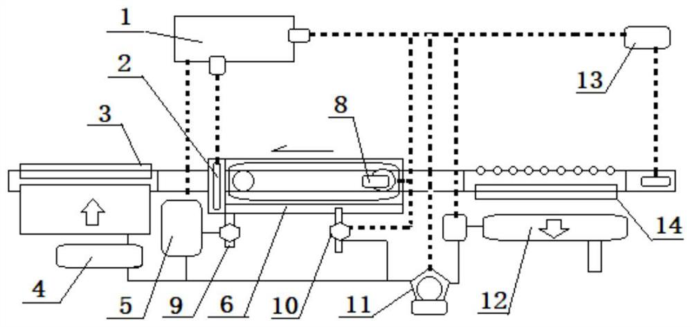
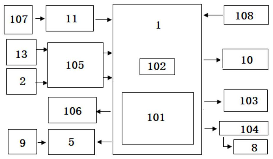
[0041] Embodiment 1: as attached figure 1 As shown, a single-chip microcomputer 1 and a power supply 11 are installed in the control equipment, and the cleaning equipment actuator includes a negative pressure dust collection box 14, an infiltration tank 6 and a dry air cushion 3 arranged in a linear order, wherein a radar sensor is installed on the negative pressure dust collection box 14 13. Install a water level sensor 2 and a cleaning motor 8 in the infiltration tank 6, and install a sewage discharge motor 5 on the sewage outlet at the bottom of the infiltration tank 6; as attached figure 2 As shown, a main controller 101 and a MOS tube 102 are installed in the single-chip microcomputer 1, and a button 108 connected to the single-chip microcomputer 1 is installed on the control device. The power supply 11, the radar sensor 13, and the water level sensor 2 are connected to the single-chip microcomputer 1. Water inlet solenoid valve 10, cleaning motor 8 and blowdown motor 5....


PUM


Abstract

The invention discloses a dynamic bearing intelligent sensing type pedestrian sole automatic cleaning device. A cleaning equipment executing mechanism comprises a negative pressure dust suction box (14), an infiltration tank (6) and a drying air cushion (3) which are linearly arranged in sequence. A radar sensor (13) is arranged on the negative pressure dust suction box (14), a water level sensor(2) and a cleaning motor (8) are installed in the infiltration tank (6), a main controller (101) and an MOS tube (102) are installed in a single chip microcomputer (1), a power source (11), a radar sensor (13) and a water level sensor (2) connected to the single chip microcomputer (1), the water level sensor (2) is connected into the single-chip microcomputer (1), and the single chip microcomputer(1) is connected with a water inlet electromagnetic valve (10), the cleaning motor (8) and a pollution discharge motor (5). Through mutual cooperation of dust collection, wetting, separation and decontamination, and air blast dehydration drying, centralized control actions are started and stopped through a sensor, and soles can be rapidly cleaned in the walking process. Dust, dirt and particle impurities embedded into anti-skid lines on the soles can be thoroughly cleaned at a time, dust collection, wetting decontamination, top blowing drying and servo work are continuously completed in the walking process, and the sole cleaning device can be easily embedded into a humanistic path channel node or walking equipment.

Description

technical field [0001] The invention relates to a structure improvement technology of an automatic shoe sole cleaning device, which belongs to IPC classification A47L23 / 00 cleaning of boots and shoes, especially A47L23 / 22, which is placed on the floor to remove soil and dust from shoes and boots. Background technique [0002] At present, the impact of possible pollution carried by shoe soles on the ground hygiene of specific environments has been widely concerned. [0003] However, in more public places, it is impossible to adopt the home state, by changing public slippers, or adopting measures such as disposable shoe covers; and, even in closed places such as some homes or offices, it is difficult to adopt the above methods. [0004] On the other hand, with the requirement to keep the ground clean in a wider range of occasions, such as hospitals, shopping malls, etc., targeted new technologies also reveal the state of technological development in this field. [0005] For e...

Claims


Application Information

Patent Timeline
Patent Type & Authority Applications(China)
IPC IPC(8): A47L23/26A47L23/20A61L2/18
CPCA47L23/20A47L23/263A61L2/18
Inventor 李运杰
Owner 万起(昆山)电子科技有限公司
Why Eureka
Try Eureka