
Tunnel boring machine and impact rock breaking cutterhead structure thereof

A technology of rock breaking and cutter head, applied in tunnels, mining equipment, earth-moving drilling, etc., can solve the problems of low rock breaking efficiency of hob fracturing, affecting tunnel construction efficiency, cutter head cutter wear and other problems

Active Publication Date: 2020-12-01
CHINA RAILWAY CONSTR HEAVY IND
View PDF5 Cites 6 Cited by
  • Summary
  • Abstract
  • Description
  • Claims
  • Application Information

AI Technical Summary

Problems solved by technology

[0006] However, in the actual excavation process, because the existing TBM belongs to rolling crushed rock, the rock is in a state of being empty on one side and compressed on three sides, and a tool is required to forcibly break the rock in a three-way compressed state. Therefore, construction in bad geology Especially in the tunnel excavation of complex hard rock and ultra-hard rock strata, the wear of the cutter head and cutter is intensified, and it needs to be replaced every day in serious cases, which consumes a lot of cost and energy consumption. The hoisting and replacement of the subsurface will seriously affect the efficiency of tunnel construction and increase the work intensity of operators, which is not conducive to the safety of tunnel construction
What's more serious is that in the case of ultra-hard rock, the efficiency of hob fracturing to break rock is extremely low, resulting in slow construction progress after conventional TBM encounters extremely hard rock

Method used


Image

  • Tunnel boring machine and impact rock breaking cutterhead structure thereof
  • Tunnel boring machine and impact rock breaking cutterhead structure thereof
  • Tunnel boring machine and impact rock breaking cutterhead structure thereof

Examples


Embodiment Construction

[0032] The following will clearly and completely describe the technical solutions in the embodiments of the present invention with reference to the accompanying drawings in the embodiments of the present invention. Obviously, the described embodiments are only some, not all, embodiments of the present invention. Based on the embodiments of the present invention, all other embodiments obtained by persons of ordinary skill in the art without making creative efforts belong to the protection scope of the present invention.

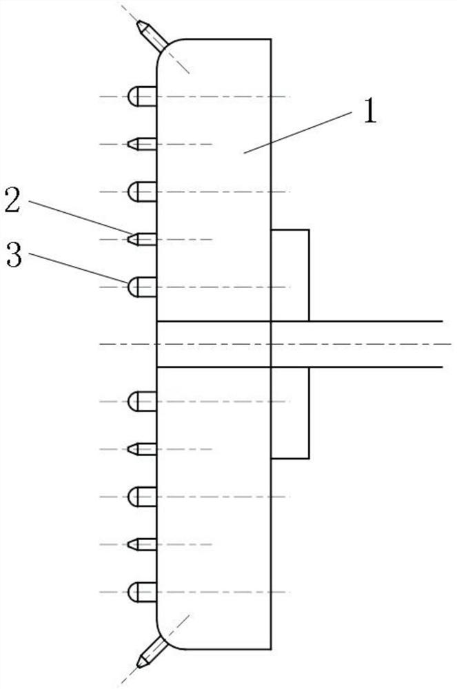
[0033] Please refer to figure 1 , figure 1 It is a schematic diagram of the overall structure of a specific embodiment provided by the present invention.

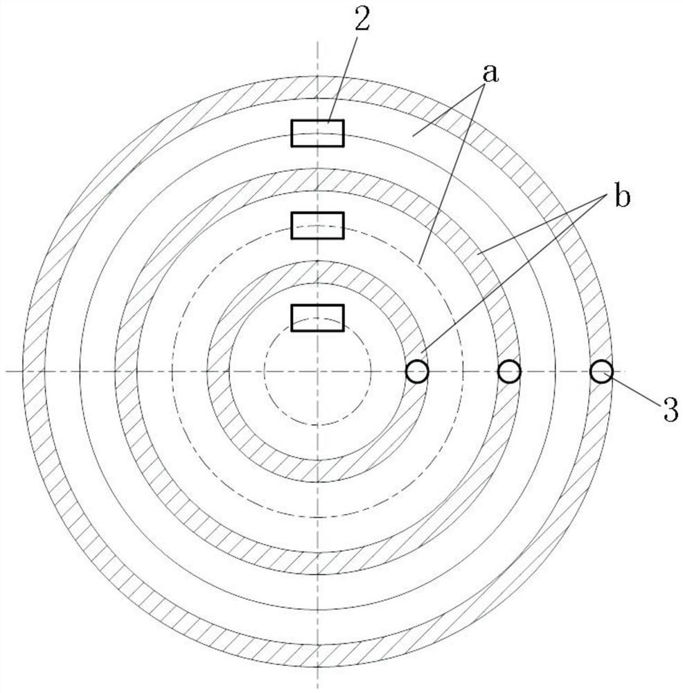
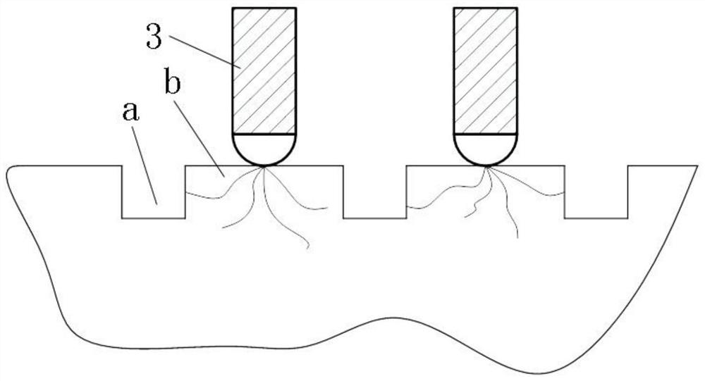
[0034] In a specific embodiment provided by the present invention, the impact rock-breaking cutter head structure mainly includes a disc body 1 , an impact assembly 2 and a rock-breaking assembly 3 .

[0035] Among them, the disc body 1 is arranged on the front end of the machine body of the tunnel boring...


PUM


Abstract

The invention discloses an impact rock breaking cutterhead structure. The impact rock breaking cutterhead structure comprises a cutterhead body which is arranged at the front end of a machine body andcan feed along the axial direction and rotate along the circumferential direction, impact assemblies arranged on cutterhead body in an axially telescopic mode, distributed in a multi-layer annular mode and used for digging a plurality of layers of annular grooves in a tunnel face along with rotation of the cutterhead body, and rock breaking assemblies arranged on the cutterhead body in an axiallytelescopic mode, distributed in a multi-layer annular mode and used for impacting and breaking annular rock layers located between every two adjacent layers of the annular grooves on the tunnel facealong with rotation of the cutterhead body. Therefore, in the tunneling process, the layers of the annular grooves are formed in a rock surface through the impact assemblies, so that rock breaking assemblies of the layers only need to overcome the weak shear strength of rock, rock surface breaking is achieved through the shear failure mode of the annular rock layers, the tunneling difficulty of rock with large compressive strength is reduced, meanwhile, the tunneling efficiency is improved, and cutter abrasion is reduced. The invention also discloses a tunnel boring machine which has the abovebeneficial effects.

Description

technical field [0001] The invention relates to the technical field of tunneling, in particular to an impact rock breaking cutter head structure. The invention also relates to a tunnel boring machine. Background technique [0002] With the development of China's machinery industry, more and more machinery and equipment have been widely used. [0003] There are many types of mechanical equipment. In civil and construction engineering, large-scale engineering equipment is usually required, such as roadheaders, excavators, and gantry cranes. Taking the shield machine as an example, the modern shield machine is a large-scale high-end tunneling equipment integrating light, mechanics, electricity and hydraulics. [0004] The cutting device of the roadheader usually includes a hob and a cutterhead. The hobs evenly arranged on the cutterhead are pressed against the rock mass under the action of propulsion. With the rotation of the hob, the rock mass is rolled out into a series of ...

Claims


Application Information

Patent Timeline
IPC IPC(8): E21D9/10
CPCE21D9/106
Inventor 廖金军蒋海华伍容孔文赵贵生许爱凤易达云
Owner CHINA RAILWAY CONSTR HEAVY IND
Learn More