Dense net support with bionic micro-thorn attachment structures

A technology of dense mesh and flat structure, applied in the field of dense mesh stents, can solve the problems of large axial elongation, difficulty in precise positioning, and easy displacement of stents, and achieve the effects of increasing roughness, enhancing adhesion, and increasing constraints

Pending Publication Date: 2020-12-04
NINGBO DIOCHANGE MEDICAL TECH CO LTD
View PDF0 Cites 2 Cited by
  • Summary
  • Abstract
  • Description
  • Claims
  • Application Information

AI Technical Summary

Problems solved by technology

However, the existing dense-mesh stent also has a series of problems. For example, the high flexibility of the dense-mesh stent can better adapt to human blood vessels, but too hi...

Method used


Image

  • Dense net support with bionic micro-thorn attachment structures
  • Dense net support with bionic micro-thorn attachment structures
  • Dense net support with bionic micro-thorn attachment structures

Examples


Embodiment 1

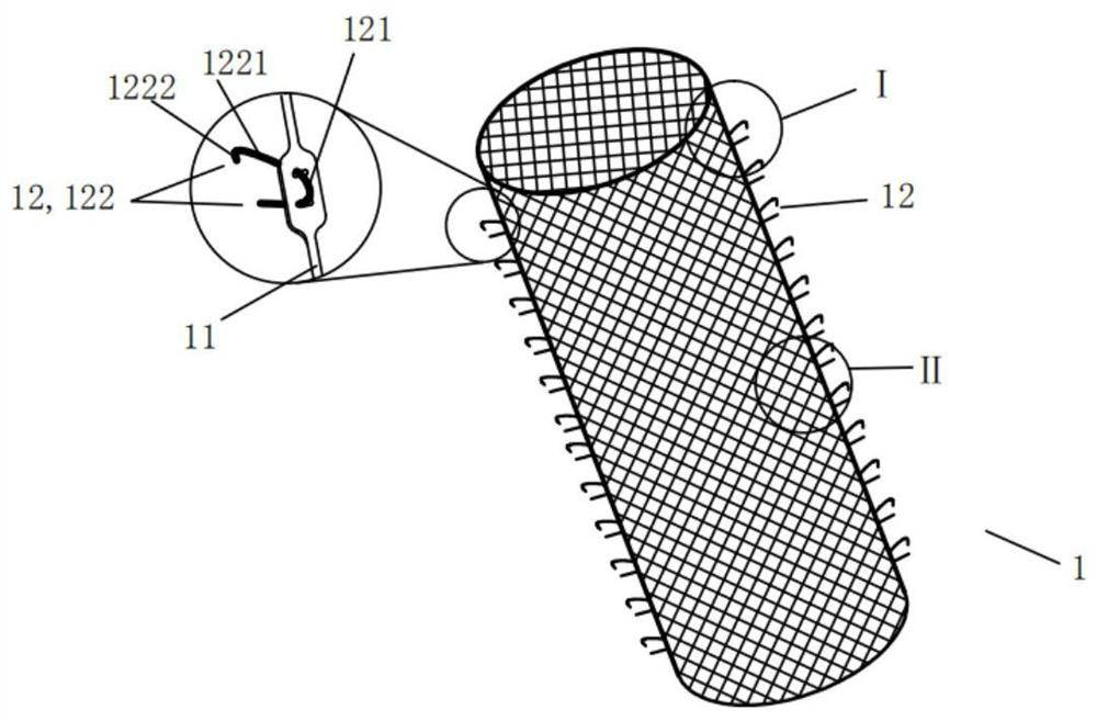
[0072] Such as figure 1 As shown, a dense mesh support 1 with a bionic micro-thorn attachment structure provided by the present invention includes an elastic skeleton 11 and a plurality of bionic micro-thorn attachment structures 12. The area of ​​the cell is 0.1 to 10mm 2 , the grid is dense and tiny, the skeleton has excellent radial compressibility, radial ductility and bending flexibility, and its diameter can be expanded from a few millimeters to tens of millimeters, not only easy to compress in the delivery sheath before operation, It can also fully fit the inner wall of the lumen when it is released during the operation, especially in some complex curved lumens with small bending radii. Morphological adaptability. The bionic micro-thorn attachment structure 12 is arranged on the outer surface of the skeleton 11. The shape of the bionic micro-thorn attachment structure 12 is the sparse micro-thorns on the surface of the imitation plant. The bionic micro-thorn attachmen...

Embodiment 2

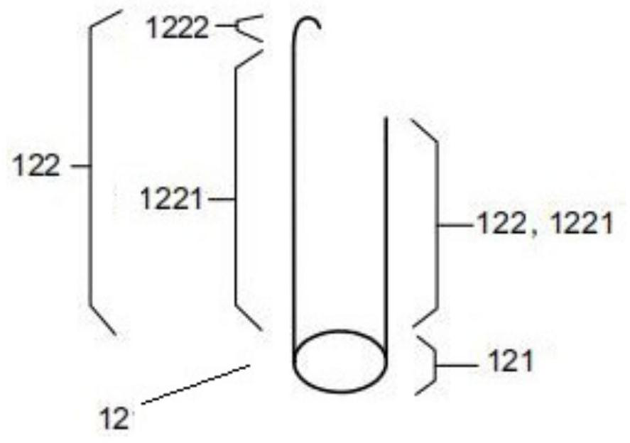
[0081] Based on the first embodiment, the design of the limiting mechanism 123 in the second embodiment is different from that in the first embodiment. In one embodiment, the limiting mechanism 123 is one or more combinations of a local constriction structure, a local protrusion structure, and a wave structure arranged on the skeleton 11, wherein the wave structure is a two-dimensional plane or a three-dimensional three-dimensional shape. One or more combinations of folding structure and serpentine structure, respectively as Figure 13 a to Figure 13 As shown in d, the bionic microthorn attachment structure 12 is formed by winding and connecting the elastic and shape-memory wire with the limit mechanism 123, wherein part of the wire is wound on the limit mechanism 123, and the free wire end to form micro-thorns 122, and the wire material involved in winding at this time is the thorn roots 121, such as Figure 14 shown. In another embodiment, the limit mechanism 123 include...

Embodiment 3

[0083] Based on Embodiment 1, the difference between Embodiment 3 and Embodiment 1 is that the skeleton 11 is made of multiple wires with elasticity and shape memory through weaving and shaping up and down, and any bionic micro-thorn attachment structure 12 is composed of a It is made of silk with elasticity and shape memory, and some or all of the wires that make the skeleton 11 are intertwined with some of the wires that make the bionic micro-thorn attachment structure 12 to achieve fixed connection. In the intertwined area The plurality of wave structures formed by the wire material for making the skeleton 11 is the limit mechanism 123, and the multiple wave structures formed by the wire material for making the bionic micro-thorn attachment structure 12 are the thorn roots 121. The free end of the wire forms micro-thorns 122. Preferably, the corrugated structure is a spatial structure formed by twisting and winding multiple wires, such as Figure 17 shown.


PUM

PropertyMeasurementUnit
Areaaaaaaaaaaa

Abstract

The invention relates to a dense net support with bionic micro-thorn attachment structures. The dense net support comprises an elastic framework and the multiple bionic micro-thorn attachment structures. The framework is a woven net pipe with a plurality of grid units, the area of any grid unit ranges from 0.1mm< 2 > to 10mm< 2 >, the framework has anatomical form adaptability, the bionic micro-thorn attachment structures are arranged on the outer surface of the framework, the form of the bionic micro-thorn attachment structures is bionic micro-thorns on the surface of a plant, each bionic micro-thorn attachment structure comprises a thorn root and a micro-thorn, each micro-thorn is composed of a thorn body and a thorn tip, each micro-thorn is in a linear shape or a J shape or a combination of the linear shape and the J shape, the thorn bodies and/or the thorn tips of the micro-thorns can make contact with the inner wall of a pipe cavity, and the attachment type anchoring function is achieved. The dense net support is wide in application range, capable of achieving accurate positioning, resistant to displacement, high in firmness and excellent in safety.

Description

technical field [0001] The invention relates to a medical device, in particular to a dense mesh support with a bionic micro-thorn attachment structure. Background technique [0002] Aneurysm is a manifestation of localized or diffuse expansion or bulging of the arterial wall due to lesion or injury of the arterial wall. , thoracoabdominal aortic aneurysm, intracranial aneurysm, aortic dissection aneurysm, visceral aneurysm, etc., mainly manifested as pulsating mass on the body surface, severe pain when the aneurysm compresses peripheral nerves or ruptures, thrombus or plaque in the tumor cavity Distal arterial embolism caused by block shedding results in ischemia or necrosis of limbs and organs. [0003] At present, the treatment of aortic aneurysm mostly uses covered stent implantation, which mainly utilizes the supporting function of the metal stent and the insulating function of the surface coating. The covered stent can effectively isolate the pressure of the blood flo...

Claims


Application Information

Patent Timeline
IPC IPC(8): A61B17/12A61F2/07
CPCA61B17/12113A61B17/12159A61B17/12168A61F2/07A61F2002/016A61F2002/061
Inventor 李彪邵烨吕世文
Owner NINGBO DIOCHANGE MEDICAL TECH CO LTD
Why Eureka
Try Eureka