Interstage sealing device for gas compressor and turbine rotor of small gas turbine

A technology for turbine rotors and gas turbines, which is applied in the direction of gas turbine devices, jet propulsion devices, components of pumping devices for elastic fluids, etc. It can solve problems such as inapplicability, and achieve the effects of easy assembly, effective and reliable sealing, and lower temperature

Pending Publication Date: 2020-12-04
上海和兰透平动力技术有限公司
View PDF0 Cites 0 Cited by
  • Summary
  • Abstract
  • Description
  • Claims
  • Application Information

AI Technical Summary

Problems solved by technology

However, the sealing device of an aerospace engine is often not suitable for the axial flow channel of this small gas turbine, so there is an urgent need for an interstage sealing device suitable for the small gas turbine compressor impeller and turbine rotor at this stage

Method used


Image

  • Interstage sealing device for gas compressor and turbine rotor of small gas turbine
  • Interstage sealing device for gas compressor and turbine rotor of small gas turbine
  • Interstage sealing device for gas compressor and turbine rotor of small gas turbine

Examples


Embodiment 1

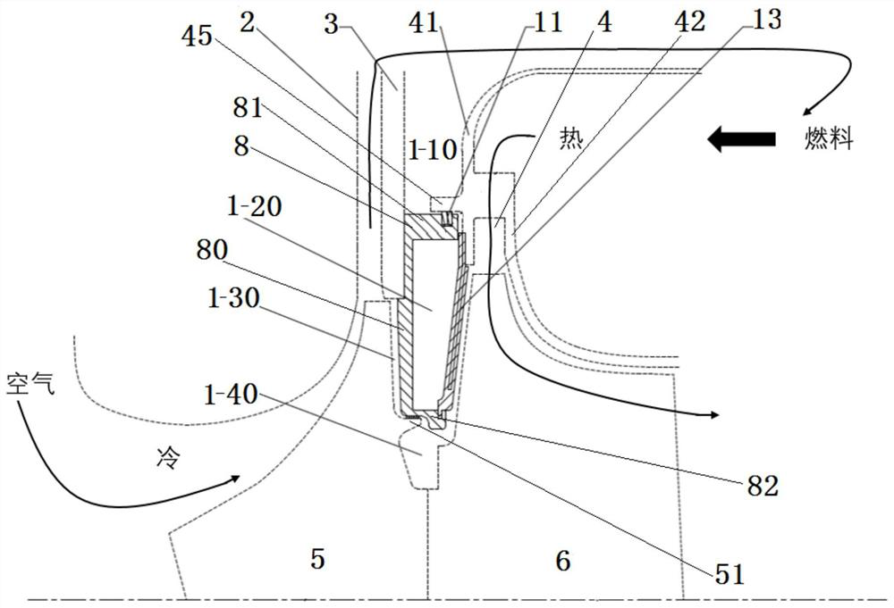
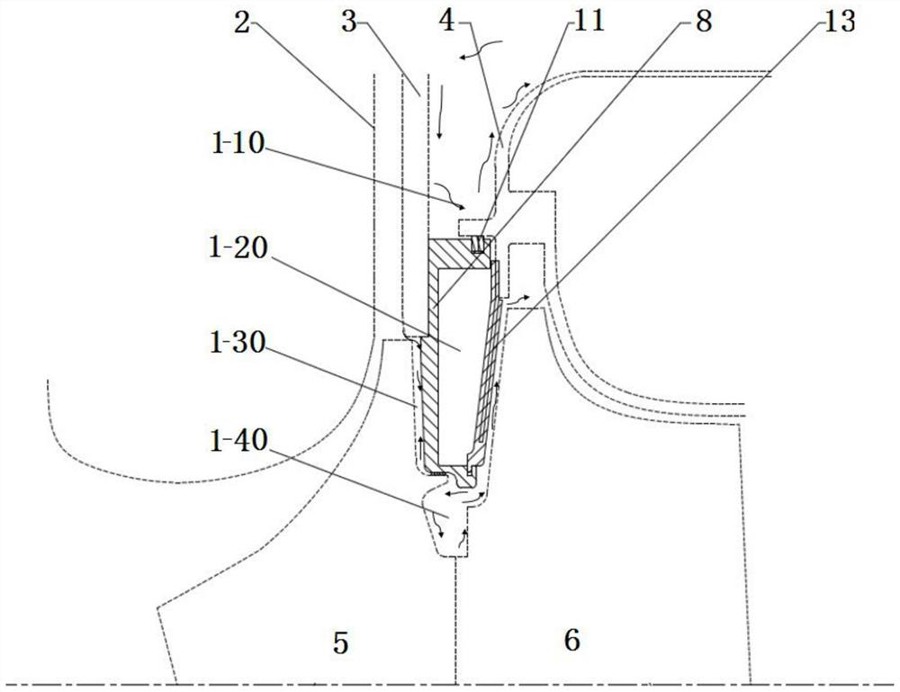
[0052] Such as figure 1 , figure 2 As shown, the diffuser 3, the sealing ring 8, and the nozzle ring 4 of the combustion chamber of the interstage sealing device of the small gas turbine compressor and the turbine rotor are all annular;

[0053] Diffuser 3, sealing ring 8, combustion chamber nozzle ring 4 are coaxially assembled with compressor impeller 5 and turbine rotor 6;

[0054] The diffuser 3 is fixed in the diffuser casing 2, and a radial cold air passage is formed between the front side of the diffuser 3 and the diffuser casing 2;

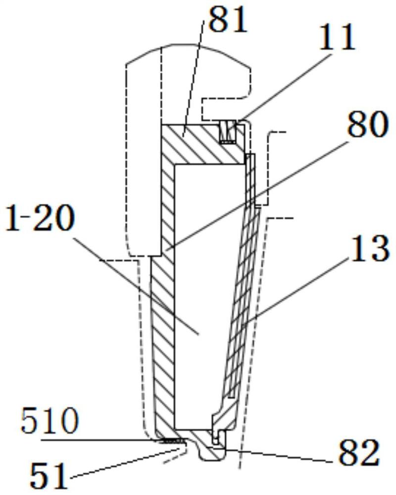
[0055] Such as image 3 As shown, the rear side of the front end wall 80 of the sealing ring 8 is formed with a coaxial far-axis ring wall 81 and a near-axis ring wall 82;

[0056] A ring of heat insulating tiles 13 is installed between the rear ends of the far-axis ring wall 81 and the near-axis ring wall 82;

[0057] The front end wall 80 of the sealing ring 8, the far-axis ring wall 81, the near-axis ring wall 82 and the heat insul...

Embodiment 2

[0070] Based on the interstage sealing device between a small gas turbine compressor and a turbine rotor in Embodiment 1, a piston ring installation groove is formed in the circumferential direction at the rear end of the far-axis ring wall 81 of the seal ring 8;

[0071] Piston ring 11 is assembled to the piston ring installation groove;

[0072] The combustion chamber nozzle ring 4 includes an outer nozzle ring 41 and an inner nozzle ring 42;

[0073] The front part of the outer nozzle ring 41 is bent radially inward, and the rear part is bent axially backward;

[0074] The front part of the inner nozzle ring 42 is bent radially outward, and the rear part is bent axially backward;

[0075] The inner nozzle ring 42 and the outer nozzle ring 41 form a hot gas injection channel;

[0076] The front end of the outer nozzle ring 41 is formed with an outer spacer ring 45 protruding forward;

[0077] The front end of the outer isolation ring 45 is sleeved outside the rear end of ...

Embodiment 3

[0080] Based on the interstage sealing device between the small gas turbine compressor and the turbine rotor in Embodiment 1, the heat insulating tile 13 is fan-shaped;

[0081] The two wings of the insulation tile 13 are respectively provided with grooves and raised ribs;

[0082] A plurality of heat-insulating tiles 13 cooperate with the ribs through the grooves, and connect end to end to form a complete sealing ring.


PUM


Abstract

The invention discloses an interstage sealing device for a gas compressor and a turbine rotor of a small gas turbine. A diffuser, a sealing ring and a combustion chamber nozzle ring of the interstagesealing device are all annular; the diffuser, the sealing ring, the combustion chamber nozzle ring, a compressor impeller and the turbine rotor are coaxially assembled together; a front end wall, a far-axis ring wall and a near-axis ring wall of the sealing ring and heat insulation tiles form an interstage sealing inner cavity; the front end wall is fixed to a near-axis part of the diffuser; a circle of inner isolating ring extending backwards is formed on a far-axis part at the rear end of the compressor impeller; a near-axis side of the near-axis ring wall is attached to a far-axis side of the isolating ring; the near-axis end of the diffuser is arranged on the far-axis side of the compressor impeller and has a radial clearance; and the far-axis ring wall of the sealing ring and the far-axis ends of the heat insulation tiles are in sealing fit with the combustion chamber nozzle ring. The interstage sealing device for the gas compressor and the turbine rotor of the small gas turbine not only can effectively reduce the temperature of the gas compressor, but also can ensure the pressure distribution of a flow path, and is simple and compact in structure, effective and reliable in sealing and easy to assemble.

Description

technical field [0001] The invention relates to a gas turbine, in particular to an interstage sealing device between a small gas turbine compressor and a turbine rotor. Background technique [0002] A gas turbine is a rotary power machine that uses continuously flowing gas as a working medium and converts the thermal energy of the working medium into mechanical work. [0003] At present, most small gas turbines (power ≤ 10MW) are designed by modification of aerospace engines, and axial flow passages are mostly used between the compressor, combustion chamber and turbine rotor. , leading to a pressure drop, it is expected that the interstage channels will not affect each other, the gas will be limited to the planned path, and the relevant parts will not be affected by the high temperature gas. However, the sealing device of an aerospace engine is often not suitable for the axial flow channel of this small gas turbine, so an interstage sealing device suitable for the small gas...

Claims


Application Information

Patent Timeline
Patent Type & Authority Applications(China)
IPC IPC(8): F02C7/28F02C3/04F02C3/14F02C7/24F01D9/04F01D9/02F04D29/44
CPCF01D9/023F01D9/041F01D9/045F02C3/04F02C3/14F02C7/24F02C7/28F04D29/441
Inventor 伍强郑冬亮吴福仙
Owner 上海和兰透平动力技术有限公司
Why Eureka
Try Eureka