Automatic displacement compensation thrust bearing

A displacement compensation and thrust bearing technology, applied in the field of thrust bearings, can solve the problems of reduced sealing performance, low propulsion efficiency, and excessive compression of the end face sealing surface.

Pending Publication Date: 2020-12-08
DONGTAI VESSEL FITTINGS
View PDF0 Cites 4 Cited by
  • Summary
  • Abstract
  • Description
  • Claims
  • Application Information

AI Technical Summary

Problems solved by technology

[0003] When the ship is moving forward, the propeller rotates in one direction to generate propulsion and acts on the thrust shaft, which will increase the static displacement of the thrust shaft along the equilibrium position in the axial direction, especially when the draft of the ship or the diving depth of the ship increases. The increase of the external water pressure at the position will generate a greater hydrostatic thrust to the cabin of the thrust shaft, causing the thrust shaft to push inward and displace, which will easily cause the phenomenon of "shaft shifting"; when the ship advances or retreats, the forward and reverse rotation of the propeller will also Make the thrust shaft produce axial inward push or outward pull
The axial displacement caused by the increase or change of the axial force of the propulsion system will have a great impact on the safe and reliable operation of the ship's propulsion system; first of all, the stern shaft sealing system, the change of the axial balance position will lead to the deterioration of the sealing performance , especially the axial displacement will cause the sealing surface of the end face to be over-pressed, the wear of the sealing surface will increase, the service life will be reduced, or the seal gap of the end face will become larger, the sealing performance will decrease, and the leakage will increase; the change of the axial balance position will also make the propeller and the position of the propeller relative to the cabin changes, the safety of the propeller operation decreases, and the propulsion efficiency becomes low; eliminating or effectively compensating for the axial displacement of the thrust shaft is particularly important for improving the propulsion performance of the ship
[0004] Axial displacement will also cause changes in the performance of propulsion system support structures and shock and noise reduction structures. When the propeller is in operation, it will generate pulsating axial thrust due to the action of the non-uniform flow field at the stern. The pulsating thrust passes through the propulsion shafting, thrust bearings, The bearing support structure and the bearing base are transmitted to the hull, and the thrust bearing system plays the role of vibration transmission carrier in the process, especially in the thrust bearing with rigid support structure, the structural vibration caused by the axial force will inevitably be The noise is transmitted to the hull of the ship, causing the excitation of the hull structure and reducing the comfort of the ship and the concealment of the warship.
[0005] At present, most of the thrust bearings on ships or boats use hydrodynamic thrust bearings or rolling element thrust bearings. Neither hydrodynamic thrust bearings nor rolling thrust bearings can compensate or adjust the axial displacement of the thrust shaft. Thrust bearings must bear huge axial thrust, and the axial displacement or axial movement of the thrust shaft is often unavoidable, which directly affects the safe and reliable operation of the ship's propulsion system

Method used


Image

  • Automatic displacement compensation thrust bearing
  • Automatic displacement compensation thrust bearing

Examples


Embodiment Construction

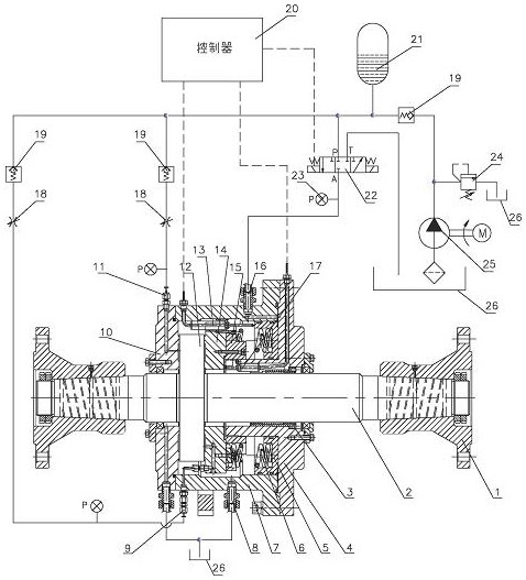
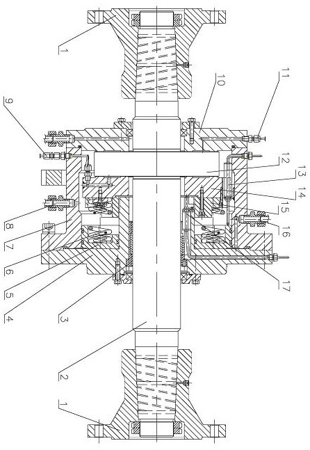
[0021] like figure 1 , figure 2 In the automatic displacement compensation thrust bearing shown, a convex disc-shaped thrust disc 12 is arranged on the thrust shaft 2, and the thrust shaft 2 and the thrust disc 12 are connected as one; Coupling 1 is a rigid coupling. The left end plate 10 and the right end plate 4 are rotatably supported on the thrust shaft 2 on the left and right sides of the thrust plate 12 through rolling bearings. Located on the center line of the bearing housing 7 , the left end plate 10 and the right end plate 4 , seals are provided on the mounting surfaces of the left end plate 10 , the right end plate 4 and the two ends of the bearing housing 7 .

[0022] A displacement compensation piston 5 is slidably arranged in the bearing housing 7. The center position of the displacement compensation piston 5 has a central through hole. The outer surface of the displacement compensation piston 5 is a cylindrical surface, and a sealing ring is arranged on the c...


PUM


Abstract

The invention discloses an automatic displacement compensation thrust bearing which comprises a thrust shaft and a thrust disc. One side of the thrust disc is supported on the inner side face of a left end plate in a sliding mode, a thrust block is supported on the other side face of the thrust disc in a sliding mode, and a displacement compensation piston is arranged in a bearing shell in a sliding mode. A compensation damping spring is supported between the thrust block and the inner end of the displacement compensation piston. A thrust block displacement sensor is arranged on the thrust block, and a piston displacement sensor is arranged on the displacement compensation piston. An oil outlet of a hydraulic pump communicates to a pressure oil port P of a hydraulic reversing valve, a portA of the hydraulic reversing valve leads to a hydraulic oil cavity between the displacement compensation piston and a right end plate, and an oil return port T of the hydraulic reversing valve is connected to an oil tank. The piston displacement sensor and the thrust block displacement sensor are electrically connected with an automatic controller, and the automatic controller is electrically connected with the hydraulic reversing valve. The automatic displacement compensation thrust bearing not only can automatically compensate axial displacement of the thrust shaft, but also can effectivelyreduce structural vibration of the bearing.

Description

technical field [0001] The invention relates to a thrust bearing of a main shaft propulsion system of a ship, in particular to a thrust bearing device capable of automatically compensating the axial displacement of a thrust shaft. Background technique [0002] Thrust bearing is the key equipment of ship shafting. Its main function is to transmit the driving power of the power plant to the propeller, and transmit the thrust or pull generated by the propeller to the hull to make the ship move forward or backward. [0003] When the ship is moving forward, the propeller rotates in one direction to generate propulsion and acts on the thrust shaft, which will increase the static displacement of the thrust shaft along the equilibrium position in the axial direction, especially when the draft of the ship or the diving depth of the ship increases. The increase of the external water pressure at the position will generate a greater hydrostatic thrust to the cabin of the thrust shaft, c...

Claims


Application Information

Patent Timeline
Patent Type & Authority Applications(China)
IPC IPC(8): B63H23/32
CPCB63H23/321B63H2023/325
Inventor 曹海健叶华崔元桃焦昌梅徐贞高邓卫翔
Owner DONGTAI VESSEL FITTINGS
Why Eureka
Try Eureka