Cloth drying device for cotton sock processing

A cloth drying and cloth technology, applied in the direction of drying, drying machine, drying gas arrangement, etc., can solve the problems that the continuous change of the position cannot be realized, and the drying process cannot be realized, so as to achieve the improvement of efficiency and adequacy, and promote the air Flow, ensure the effect of drying effect

Inactive Publication Date: 2020-12-08
诸暨市佳叶袜业有限公司
View PDF1 Cites 8 Cited by
  • Summary
  • Abstract
  • Description
  • Claims
  • Application Information

AI Technical Summary

Problems solved by technology

[0003] The patent application publication number CN110044150 A discloses a cloth drying device for textile processing, including a base plate, the top of the base plate is fixedly connected with a motor compartment, and the top of the motor compartment is fixedly connected with a drying compartment, and A heating bin is arranged above the motor bin, and the heating bin is located in a drying bin. A bin door is inst...

Method used


Image

  • Cloth drying device for cotton sock processing
  • Cloth drying device for cotton sock processing
  • Cloth drying device for cotton sock processing

Examples


Embodiment 1

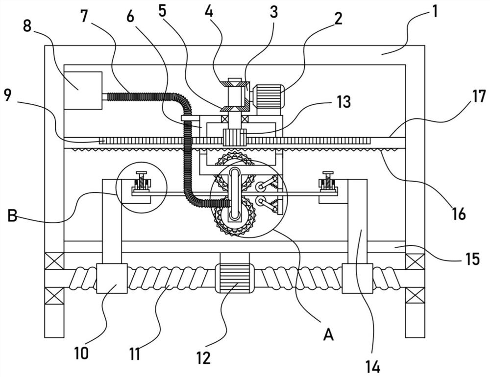
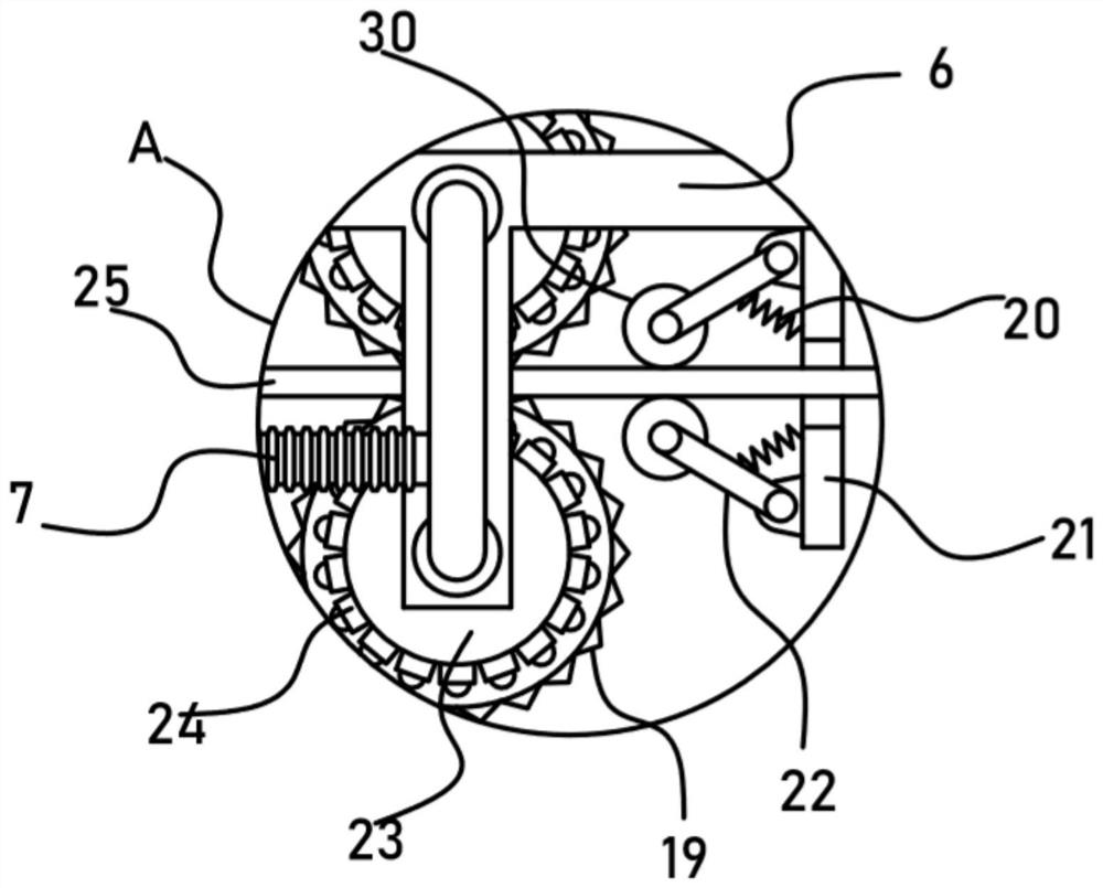
[0022] see Figure 1-4 , a cloth drying device for cotton socks processing, including a support frame 1, a biaxial motor 12 and a hot air blower 8 are fixed on the support frame 1, the biaxial motor 12 is driven and connected with a transverse translation mechanism, and the transverse translation mechanism is There is a clamping mechanism for clamping the cloth 25, a horizontal plate 17 is fixed horizontally on the support frame 1, and a moving frame 6 is slidably sleeved on the horizontal plate 17. For the drying mechanism for drying, the moving frame 6 is provided with a reciprocating mechanism for driving its lateral reciprocating motion, and the bottom of the moving frame 6 is provided with a rolling mechanism for flattening the cloth 25 .

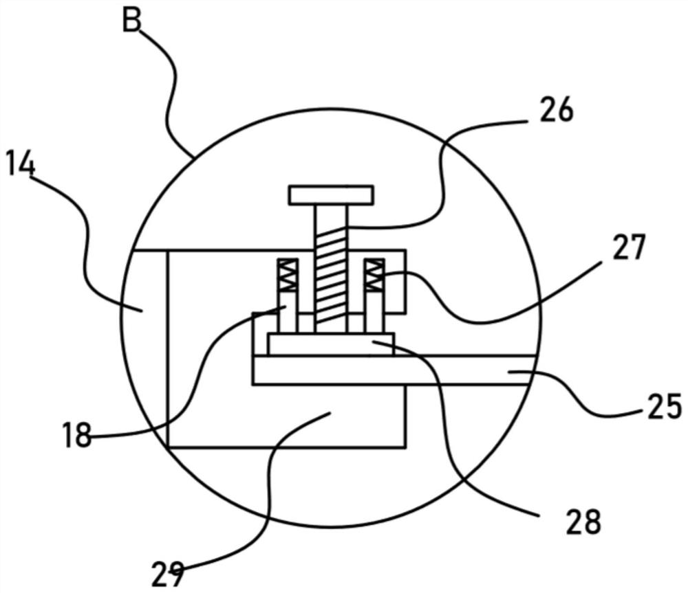
[0023] The device can adjust the distance between the two vertical plates 14 through the provided lateral translation mechanism, so that the two clamping mechanisms can be brought close to each other, and the tension effect after clamp...

Embodiment 2

[0031] On the basis of Embodiment 1, in addition, the reciprocating mechanism of the device includes a drive motor 2 fixed on the moving frame 6 , an incomplete bevel gear 3 is drivingly connected to the drive motor 2, and a rack is fixed on the horizontal plate 17 I9, the rack I9 is ​​meshed with a transmission gear 13, and the transmission gear 13 is coaxially fixed with a bevel gear I4 and a bevel gear II5 that are alternately meshed with the incomplete bevel gear 3.

[0032] Through the above settings, the drive motor 2 drives the incomplete bevel gear 3 to rotate, and the incomplete bevel gear 3 is meshed with the bevel gear I4 and the bevel gear II5 alternately. At this time, the transmission gear 13 rotates alternately clockwise and counterclockwise. Under the meshing action of I9, the moving frame 6 is driven to reciprocate laterally, so as to realize the lateral reciprocating translation of the drying mechanism, so as to fully dry the cloth 25 at different lateral posi...


PUM


Abstract

The invention discloses a cloth drying device for cotton sock processing, and relates to the technical field of cotton sock production. The cloth drying device comprises a supporting frame, a double-shaft motor and an air heater are fixed to the supporting frame, a drying mechanism used for drying cloth is rotationally installed on a movable frame, a reciprocating mechanism used for driving the movable frame to do transverse reciprocating motion is arranged on the movable frame, and a rolling mechanism for flattening the cloth is arranged at the bottom of the movable frame. Hot air generated by the air heater is blown through spray heads in the drying mechanism, the air blowing drying effect on the cloth is achieved, the reciprocating mechanism can drive the movable frame to do transversereciprocating motion, the drying mechanism can do transverse reciprocating motion, sufficient drying treatment on different positions of the cloth is achieved, meanwhile, in the moving process, hollowrotating rollers can achieve a rotating effect, air flowing around the cloth is effectively promoted, the sufficient drying effect on the cloth is guaranteed, and the drying efficiency and the dryingsufficiency are remarkably improved.

Description

technical field [0001] The invention relates to the technical field of cotton socks production, in particular to a cloth drying device for cotton socks processing. Background technique [0002] Socks are clothing items worn on the feet. "Shuowen": "韤, foot clothing is also." It plays the role of protecting feet and preventing foot odor. Socks are a general term. According to the raw materials, there are cotton yarn socks, wool socks, stockings and various chemical fiber socks, etc. According to the shape, there are stockings, mid-tube socks, boat socks, pantyhose, etc. With, without heel and jacquard, weaving and other styles and varieties. In the production and processing of cotton socks, the fabric used needs to be dried. [0003] Patent Application Publication No. CN110044150 A discloses a cloth drying device for textile processing, including a bottom plate, a motor compartment is fixedly connected to the top of the bottom plate, and a drying compartment is fixedly con...

Claims


Application Information

Patent Timeline
IPC IPC(8): F26B9/06F26B5/14F26B21/00F26B25/00F26B25/18F26B25/20D06C15/02
CPCD06C15/02D06C2700/09F26B5/14F26B9/06F26B21/004F26B25/001F26B25/185F26B25/20
Inventor 袁润栋
Owner 诸暨市佳叶袜业有限公司
Why Eureka
Try Eureka