Signal quality stable output circuit of infrared detector

A technology for infrared detectors and signal quality, applied in electrical radiation detectors, televisions, electrical components, etc., can solve problems such as abnormal operation of detectors, affecting the reset of integrating capacitors, NETD of infrared detectors, and non-uniformity differences, etc. Real-time configuration, stable image signal output effect

Inactive Publication Date: 2020-12-08
SHANGHAI AEROSPACE CONTROL TECH INST
View PDF6 Cites 1 Cited by
  • Summary
  • Abstract
  • Description
  • Claims
  • Application Information

AI Technical Summary

Problems solved by technology

According to the working mechanism value of the detector, the beating of VR directly affects the reset of the integrating capacitor, resulting in abnormal output; at the same time, the change of the bias voltage of the photovoltaic diode will cause the beating of dark current, which will also lead to abnormal output
The actual military environment has to deal with different working conditions, so the dark current will also change with the change of temperature. At the same time, due to its process, materials and other reasons, the change of dark current is more obvious at different temperatures, showing different response characteristics. curve, the difference of this kind of curve under different integrals will be enlarged, and in severe cases, it will cause the detector to work abnormally
[0004] At present, most infrared detector power supply circuits only provide a stable capacitor reset voltage and photovoltaic diode bias voltage, which makes the NETD and non-uniformity of infrared detectors show great differences at different temperatures

Method used


Image

  • Signal quality stable output circuit of infrared detector
  • Signal quality stable output circuit of infrared detector
  • Signal quality stable output circuit of infrared detector

Examples


Embodiment Construction

[0033] Exemplary embodiments of the present disclosure will be described in more detail below with reference to the accompanying drawings. Although exemplary embodiments of the present disclosure are shown in the drawings, it should be understood that the present disclosure may be embodied in various forms and should not be limited by the embodiments set forth herein. Rather, these embodiments are provided for more thorough understanding of the present disclosure and to fully convey the scope of the present disclosure to those skilled in the art. It should be noted that, in the case of no conflict, the embodiments of the present invention and the features in the embodiments can be combined with each other. The present invention will be described in detail below with reference to the accompanying drawings and examples.

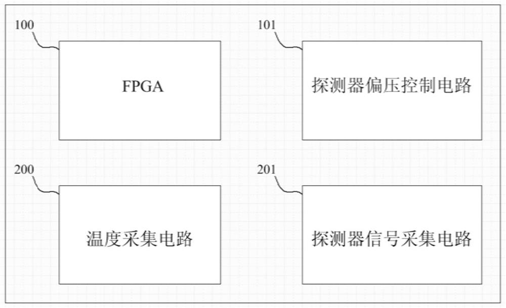
[0034] figure 1 It is a structural block diagram of the external detector signal quality stable output circuit of the present invention. Such as figure 1 A...


PUM


Abstract

The invention discloses a signal quality stable output circuit of an infrared detector. The signal quality stable output circuit comprises a main processor FPGA, a temperature acquisition circuit, a detector bias control circuit and a detector signal acquisition circuit; the temperature acquisition circuit acquires the working environment temperature of the infrared detector, digitalizes the temperature and sends the digitalized temperature to the main processor FPGA; the main processor FPGA updates a detector bias voltage working instruction according to the temperature acquired by the temperature acquisition circuit and sends the detector bias voltage working instruction to the detector bias voltage control circuit; the detector bias control circuit updates the working voltage VR and Vgpol of the infrared detector according to a detector bias working instruction. The detector signal acquisition circuit corrects an output analog image signal according to the working voltage VR and Vgpol of the infrared detector, digitizes the analog image signal and sends the digitized analog image signal to the main processor FPGA. Acquisition of the environment temperature is completed through the temperature acquisition circuit, the acquired temperature is used as guidance, prior information is read, the detector bias voltage is configured through the detector bias voltage control circuit,bias voltage real-time configuration is achieved, and image signal output is stabilized.

Description

technical field [0001] The invention belongs to the technical field of microelectronics and optoelectronics, and in particular relates to an infrared detector signal quality stable output circuit. Background technique [0002] Infrared imaging technology is a research hotspot in the world today both in military and civilian fields. Especially in the military field, due to the passive detection characteristics of infrared detection itself, it has good concealment and anti-interference ability. At the same time, due to the long detection distance and the ability to work day and night, infrared technology has been widely used in the military field. [0003] The infrared detector working power supply circuit and readout circuit are the core components of the infrared imaging system, which are used to provide the stable working voltage of the infrared detector and collect the output signal of the infrared detector. According to the working mechanism value of the detector, the be...

Claims


Application Information

Patent Timeline
Patent Type & Authority Applications(China)
IPC IPC(8): G01J5/24H04N5/33
CPCG01J5/24H04N5/33
Inventor 苗壮龚瑞关智聪蔡彬李宁珍刘建旭蒋颖晖
Owner SHANGHAI AEROSPACE CONTROL TECH INST
Why Eureka
Try Eureka