A multifunctional therapeutic catheter

A multi-functional catheter technology, applied in the field of medical devices, can solve problems such as long suction time, small thrombus falling off, and unfavorable recovery of patients, so as to reduce the cost borne by patients and medical insurance costs, reduce the probability of thrombus escape, and improve the blood vessel. The effect of open rate

Active Publication Date: 2021-10-15
玮铭医疗器械(上海)有限公司
View PDF10 Cites 0 Cited by
  • Summary
  • Abstract
  • Description
  • Claims
  • Application Information

AI Technical Summary

Problems solved by technology

[0004] Existing thrombectomy stents are generally laser-engraved, and the surface is made of different grids. The thrombus is embedded in the mesh of the stent, and its clamping force is relatively limited. During the thrombectomy process, the thrombus is easy to fall off or break from the thrombus retrieval stent. A small thrombus is formed and falls off. Under the action of blood flow, it escapes to a small blood vessel farther away, and will not be able to recapture the thrombus, resulting in the risk of secondary stroke. Negative pressure in the lumen, because the diameter of the tube body is limited by the diameter of the blood vessel, the nozzle is generally small, the suction force is not enough, and the suction time is long, causing a lot of pain to the patient; the existing thrombectomy cannot be performed simultaneously with the stent (mechanical) Plugs and Catheter Suction Plugs
In addition, it has been found from relevant literature that after using catheter suction, stent retrieval is needed again for up to 65% of the cases. Once rescue is used, a microcatheter must be added to deliver the thrombectomy stent, which is troublesome for doctors to operate. The operation time is long, which is not conducive to the recovery of the patient, and the cost borne by the patient is also high

Method used


Image

  • A multifunctional therapeutic catheter
  • A multifunctional therapeutic catheter
  • A multifunctional therapeutic catheter

Examples


Embodiment 1

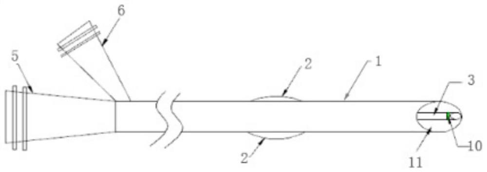
[0040] like figure 1 , image 3 As shown, Embodiment 1 of the present invention provides a multifunctional treatment conduit, a catheter body 1, and a balloon 2 covering the outer wall of the catheter body 1, a micropipe 3, and a microcatheter 3 The inner hollow is formed, and the inlet 5 is provided in the proximal end portion of the catheter body 1, and a charging inlet 6 is also provided on one side of the proximal end portion of the catheter body 1; wherein the The catheter body 1 is a three-cavity catheter that is incapaches, including the suction cavity channel 7, the charging cavity channel 8, and the microconplant passage 4, and the suction cavity channel 7 communicates with the suction inlet 5, the charging The cavity channel 8 is in communication with the charging inlet 6.

[0041] The suction cavity channel 7 and the charging cavity channel 8 are disposed along the central axis of the center of the conduit body 1, and the micropal conduit inner track is located inside th...

Embodiment 2

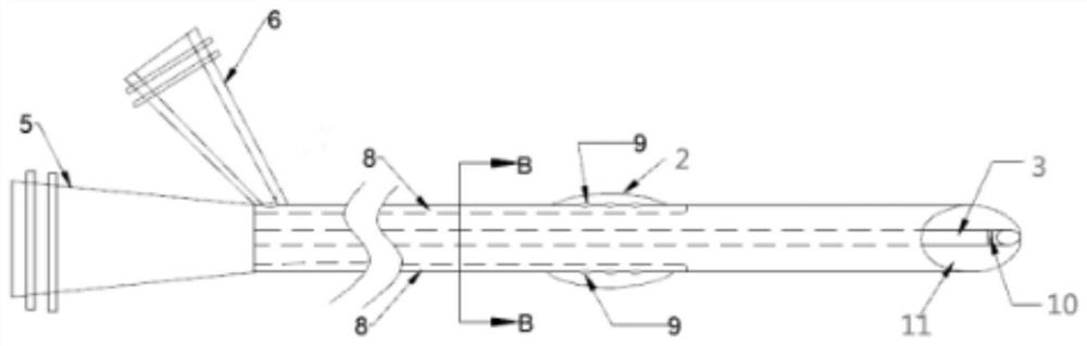
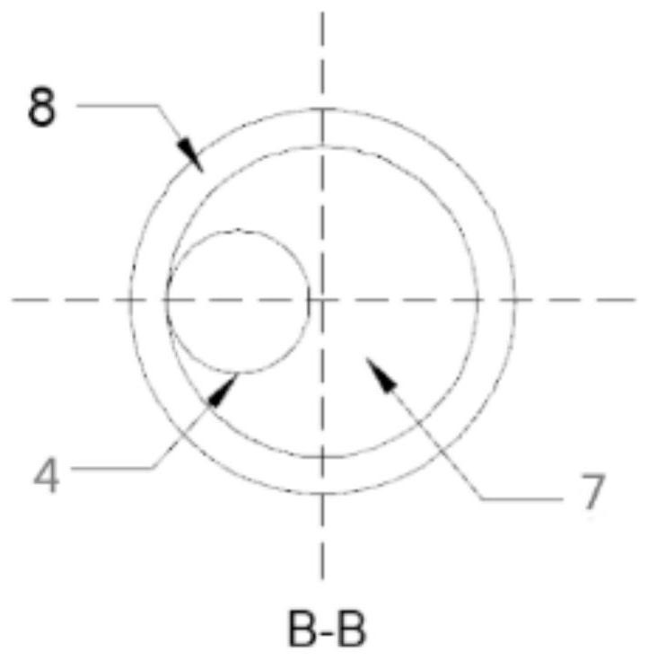
[0044] like Figure 1 ~ 3 As shown, Embodiment 2 of the present invention provides a multifunctional treatment conduit, a catheter body 1, and a balloon 2 covering the outer wall of the catheter body 1, which is provided with a microdynamic tube 3, and the microcatheter 3 The inner hollow is formed, and the inlet 5 is provided in the proximal end portion of the catheter body 1, and a charging inlet 6 is also provided on one side of the proximal end portion of the catheter body 1; wherein the The catheter body 1 is a three-cavity catheter that is incapaches, including the suction cavity channel 7, the charging cavity channel 8, and the microconplant passage 4, and the suction cavity channel 7 communicates with the suction inlet 5, the charging The cavity channel 8 is in communication with the charging inlet 6.

[0045] The suction cavity channel 7 and the charging cavity channel 8 are disposed along the central axis of the center of the conduit body 1, and the micropal conduit inner...

Embodiment 3

[0049] like Figure 4 ~ 5 As shown, Embodiment 3 of the present invention provides a multifunctional treatment catheter kit, including the multi-functional treatment catheter shown in Example 2, and syringe 12 and connection valve 13 used with multifunctional treatment catheter, by microcatheter Internal endolic bracket 14; the syringe 12 is detachably disposed on the charging inlet 6 to charge the balloon 2, so that the proximal blood flow is blocked to prevent the suppression process, blood Escape to the distal blood vessel; the connection valve is the Y valve, and one end of the Y valve is connected to a suction pump. When the pump is turned on, the catheter body sucks the inner cavity to produce a negative pressure, and the oblique cutting port begins to start Vehicle tissue.

[0050] like Figure 4 As shown, it is a schematic diagram of the catheter kit during the suppression. When the catheter body 1 is guided by the DSA, the distal port reaches the thrombus position; the ball...


PUM


Abstract

The invention relates to the field of medical devices, in particular to a multifunctional treatment catheter. A multi-functional therapeutic catheter, comprising a catheter body and a balloon coated on the outer wall of the catheter body, a microcatheter is arranged inside the catheter body, and the microcatheter is hollow inside to form a microcatheter lumen, near the catheter body The end is provided with a suction inlet, and one side of the proximal end of the catheter body is also provided with a pressure inlet; wherein, the catheter body is a three-lumen catheter that does not communicate with each other, including a suction lumen, a pressure lumen And the inner lumen of the microcatheter, the suction lumen communicates with the suction inlet, and the pressurization lumen communicates with the pressurization inlet. The catheter can also deliver a thrombectomy stent for mechanical thrombectomy. When catheter suction is performed, stent thrombectomy can be performed at the same time, which shortens the operation time and reduces the cost borne by the patient and medical insurance costs.

Description

Technical field [0001] The present invention belongs to the field of medical devices, and more particularly, the present invention relates to a multifunctional treatment catheter. Background technique [0002] Cardiovascular embolism may cause a honestry, stroke diseases, have a huge threat to human life and health, and current main treatment methods include bracket (machinery) ejecting, catheter suction methods, etc. Mechanical ejecting and catheter suction are taken from the human blood vessel by physical methods, thereby re-passing the blood vessels and restores the normal flow of blood to achieve the purpose of treatment. [0003] The main principle of mechanical ejector is to send an endolic bracket made of a memory alloy material to a lesion position in a guide wire, a conduit, and capture and pull the blood into the catheter after the bolt bracket is removed. The catheter suction is passed through a balloon blocking guide (or guide guide), the micrilization is delivered to...

Claims


Application Information

Patent Timeline
Patent Type & Authority Patents(China)
IPC IPC(8): A61B17/22
CPCA61B17/22A61B2017/22062A61B2017/22067A61B2017/22079
Inventor 吴健平赵杰曹维拯何家乐李志刚王国辉
Owner 玮铭医疗器械(上海)有限公司
Why Eureka
Try Eureka