Safe and sanitary sprayer
A sprayer and hygienic technology, which is applied in the direction of the atomizer for treatment, the container for dressing, the container for cosmetic powder, etc., can solve the problems of increased pollution frequency, cosmetic pollution, pollution quality, etc., to reduce waste, reduce pollution, reduce The effect of pollution
- Summary
- Abstract
- Description
- Claims
- Application Information
AI Technical Summary
Problems solved by technology
Method used
Image
Examples
Embodiment 1
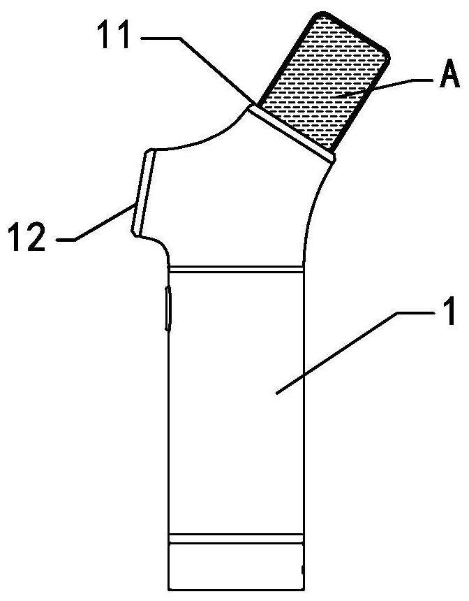
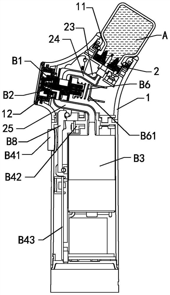
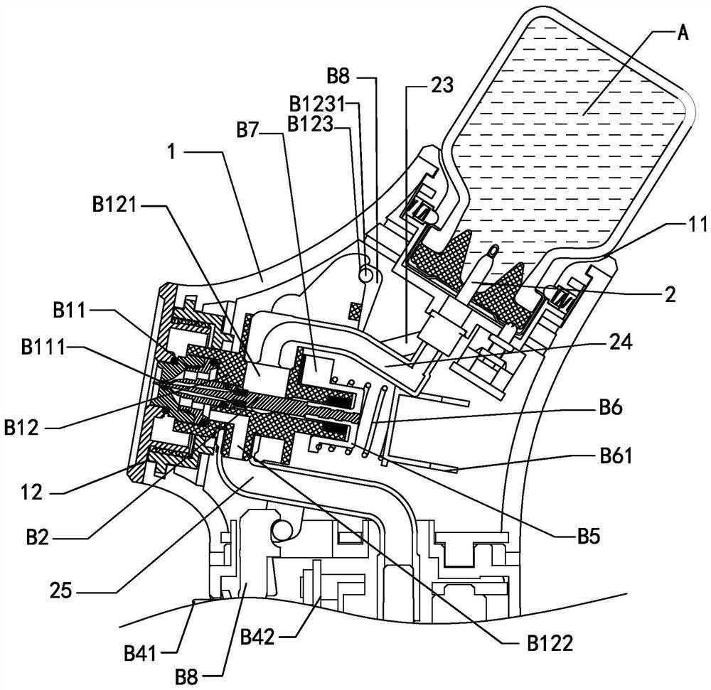
[0038] see Figure 1-9 , This embodiment provides a safe and hygienic sprayer, including a housing 1, a liquid-feeding needle 2 and a spray assembly. The housing 1 is provided with an installation port 11 and a nozzle 12, the liquid inlet needle 2 is set in the installation port 11, and the ampoule A is installed at the installation port 11, so that the liquid inlet needle 2 can pierce the cap of the ampoule A , a liquid inlet channel 21 is opened on the liquid inlet needle 2. After the liquid inlet needle 2 punctures the ampoule A, one end of the liquid inlet channel 21 is located inside the ampoule A, and the other end of the liquid inlet channel 21 is located outside the ampoule A and passes through the liquid inlet The tube 24 is connected to the spray assembly which sprays at the nozzle 12 when the sprayer is in operation.
[0039] Wherein the sprayer also includes an ampoule seat, the ampoule seat is installed in the installation port 11, the inner wall of the housing 1...
Embodiment 2
[0058] see Figure 10-14 , The first difference between this embodiment and Embodiment 1 is that the nebulizer also includes an air filter B9.
[0059] The ampoule seat B91 is installed in the installation port 11, and the ampoule seat B91 and the inner wall of the installation port 11 are clamped. The ampoule A is installed at the installation port 11 through the ampoule seat B91, and the ampoule A is supported by the ampoule seat B91. The liquid inlet needle 2 passes through the ampoule seat B91, and the liquid inlet needle 2 is positioned by the ampoule seat B91 to ensure that the liquid inlet needle 2 can pierce the ampoule A and prevent the ampoule A from shaking at the installation port 11 as much as possible , to avoid leakage of ampoule A.
[0060] The air filter B9 is installed on the side wall of the ampoule seat B91 away from the ampoule A, and the ampoule seat B91 is provided with an air inlet B911 and an air outlet B912. The air inlet B911 is connected to the i...
Embodiment 3
[0069] see Figure 15, The difference between this embodiment and Embodiment 2 is that the spray assembly retains the valve seat B1 and omits the electromagnet and the valve core, so the spray port B111 remains normally open. The spray assembly of this embodiment also includes an inlet valve B14 connected between the valve seat B1 and the air filter B9 and a liquid inlet valve B13 connected between the liquid inlet channel and the liquid inlet, and the micro switch B42 is activated, the air filter The device B9, the atomizing air pump B3, the air inlet valve B14 and the liquid inlet valve B13 are all electrically connected to the control board, so that the air filter B9 and the air inlet valve B14 are closed with a delay relative to the liquid inlet valve B13. The outlet of the air filter B9 is also connected to the liquid flow path. For a period of time after the atomization air pump B3 and the liquid inlet valve B13 are closed, the air filter B9 and the air inlet valve B14 ...
PUM
 Abstract
Description
Claims
Application Information
 - R&D
- Intellectual Property
- Life Sciences
- Materials
- Tech Scout
- Unparalleled Data Quality
- Higher Quality Content
- 60% Fewer Hallucinations
Browse by: Latest US Patents, China's latest patents, Technical Efficacy Thesaurus, Application Domain, Technology Topic, Popular Technical Reports.
© 2025 PatSnap. All rights reserved.Legal|Privacy policy|Modern Slavery Act Transparency Statement|Sitemap|About US| Contact US: help@patsnap.com


