Power semiconductor device for testing gate pole current

A technology of power semiconductors and gates, which is applied in semiconductor devices, electric solid-state devices, semiconductor/solid-state device components, etc., can solve the problems of chip design structure and parameter obstacles, and the inability to distinguish the gate current of thyristor chips, etc., to achieve guarantees, etc. effect of efficacy

Active Publication Date: 2020-12-11
TSINGHUA UNIV
View PDF6 Cites 2 Cited by
  • Summary
  • Abstract
  • Description
  • Claims
  • Application Information

AI Technical Summary

Problems solved by technology

Numerous ring-shaped cathode strip electrodes arranged at intervals in the chip are in contact with the inner and outer cathode contact sheets in the cathode casing, and the gate ring electrode is in contact with the gate contact ring in the cathode casing, because the gate ring electrode is in contact with the chip The common gate metal area below the inner second insulating layer 55 is connected, so the gate current of the chip has only a single ring-shaped lead-out end, so it is impossible to distinguish the gate currents of different cathode strip regions inside the thyristor chip
Therefore, due to the limitation of the sealing of the traditional power semiconductor device, the further understanding of the failure mechanism of the internal chip and the optimized chip design structure and parameters have brought great obstacles

Method used


Image

  • Power semiconductor device for testing gate pole current
  • Power semiconductor device for testing gate pole current
  • Power semiconductor device for testing gate pole current

Examples


Embodiment Construction

[0032] In order to make the purpose, technical solutions and advantages of the embodiments of the present invention more clear, the technical solutions in the embodiments of the present invention will be clearly and completely described below in conjunction with the accompanying drawings in the embodiments of the present invention. Obviously, the described embodiments It is a part of embodiments of the present invention, but not all embodiments. Based on the embodiments of the present invention, all other embodiments obtained by persons of ordinary skill in the art without making creative efforts belong to the protection scope of the present invention.

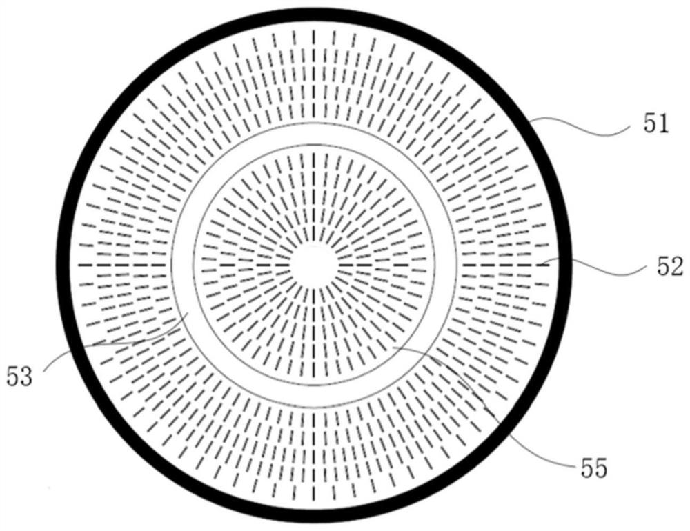
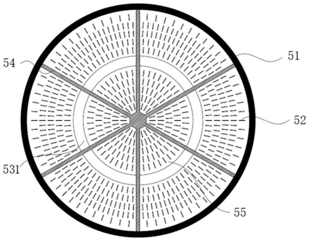
[0033] An embodiment of the present invention introduces a power semiconductor device for testing gate current, including a power semiconductor chip and a casing, the power semiconductor chip includes a plurality of first insulating layers and a plurality of sub-gate ring electrodes, the The first insulating layer divides the ...


PUM


Abstract

The invention discloses a power semiconductor device for testing a gate pole current. The device comprises a power semiconductor chip and a tube shell. The power semiconductor chip comprises a plurality of first insulating layers and a plurality of sub gate pole annular electrodes; the first insulating layers divide a gate pole common metal region of the power semiconductor chip into a plurality of sub gate pole common metal regions, and the plurality of sub gate pole common metal regions are connected with the plurality of sub gate pole annular electrodes in a one-to-one correspondence manner; the tube shell comprises a plurality of sub gate pole contact rings and a plurality of sub-insulating seat inner metal rings, and the sub gate pole contact rings and the sub insulating seat inner metal rings are arranged with the plurality of sub gate pole annular electrodes in a one-to-one correspondence manner; and a plurality of square grooves are formed in a cathode copper block on the outerside of a tube shell gate pole groove, and gate pole leading-out strips are arranged in the square grooves so as to lead out gate pole currents on the corresponding sub gate pole annular electrodes respectively. The power semiconductor device can effectively lead out gate pole currents of different cathode strip-shaped areas in the power semiconductor chip so as to achieve a purpose of measurement.

Description

technical field [0001] The invention belongs to the field of power electronics, in particular to a power semiconductor device for testing gate current. Background technique [0002] Power semiconductor devices mainly include three parts: power semiconductor chips, low-inductance casings, and control drives. In traditional power semiconductor devices, the anode copper block and the anode welding ring are welded together to form the anode shell, and the cathode copper block, the cathode welding ring, the cathode lead-out ring, the lower ceramic, the gate lead-out ring, the upper ceramic and the anode welding on the upper ceramic The rings are welded together to form the cathode shell, and the remaining gate components include the gate disc spring, the metal ring under the insulating seat, the gate insulating seat, and the metal ring inside the insulating seat are placed in the gate groove of the cathode shell in sequence. Finally, install the inner cathode contact piece, the ...

Claims


Application Information

Patent Timeline
Patent Type & Authority Applications(China)
IPC IPC(8): G01R19/00H01L23/544
CPCG01R19/0092H01L22/32
Inventor 赵彪周文鹏曾嵘余占清陈政宇刘佳鹏
Owner TSINGHUA UNIV
Why Eureka
Try Eureka