
A Broadband Circularly Polarized Filter Array Antenna with Sequential Rotational Feed

A sequential rotation, filter array technology, applied in the direction of the separately powered antenna array, specific array feeding system, antenna, etc., can solve problems such as poor matching and reduced gain, reduce structural complexity, and increase axial ratio bandwidth. , The effect of circular polarization characteristic optimization

Active Publication Date: 2021-04-13
上海东洲罗顿通信股份有限公司
View PDF20 Cites 0 Cited by
  • Summary
  • Abstract
  • Description
  • Claims
  • Application Information

AI Technical Summary

Problems solved by technology

Traditional design methods usually design the antenna and filter as independent parts and then cascade them, or combine the filter with the feed network. These methods will have problems such as poor matching, insertion loss, and reduced gain.

Method used


Image

  • A Broadband Circularly Polarized Filter Array Antenna with Sequential Rotational Feed
  • A Broadband Circularly Polarized Filter Array Antenna with Sequential Rotational Feed
  • A Broadband Circularly Polarized Filter Array Antenna with Sequential Rotational Feed

Examples


Embodiment Construction

[0042] The present invention is further analyzed below in conjunction with specific examples.

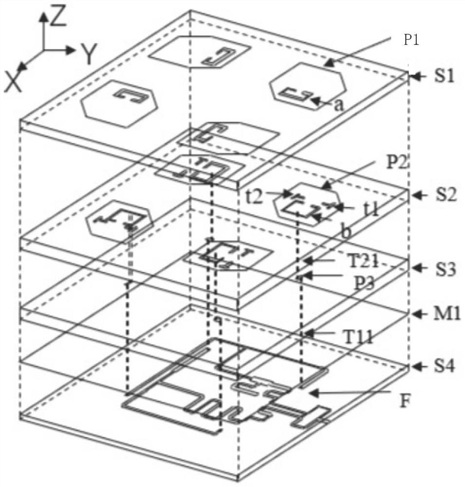
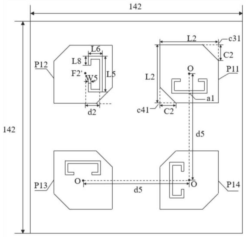
[0043] to combine figure 1 and figure 2 , a broadband circularly polarized filter array antenna with sequential rotating feed, including dielectric substrates S1, S2, S3, S4 and feeding structures with different thicknesses arranged sequentially from top to bottom; a dielectric substrate S1 and a dielectric substrate S2 are arranged between There is an air layer with a height h3, and the second dielectric substrate S2, the third dielectric substrate S3 and the fourth dielectric substrate S4 are arranged in contact. A metal layer M1 of the same size is provided between the dielectric substrate S3 and the dielectric substrate S4 as a ground plane.

[0044] Dielectric substrate S1 adopts Rogers5880 dielectric substrate with thickness h2, dielectric substrate S2 adopts Rogers5880 dielectric substrate with thickness h1, dielectric substrate S3 adopts Rogers5880 dielectric substrate wi...


PUM


Abstract

The invention discloses a broadband circularly polarized filter array antenna with sequential rotating feed. The structure of the present invention cuts the diagonals of the square patch and introduces degenerate mode separation to realize the circularly polarized antenna unit; then, by etching open resonant rings of different sizes on the surface of the patch, gain zero points are respectively introduced on both sides of the working frequency band to achieve better out-of-band suppression; and by adding parasitic patches, opening T-slots, adopting strip line-probe hybrid feeding structure and sequential rotating feeding technology, the relative bandwidth is 43.14%, the axial ratio bandwidth is 1.71%, and the highest gain reaches 14.64dBi 2×2 circularly polarized antenna array.

Description

technical field [0001] The invention belongs to the technical field of antenna design of wireless communication technology, in particular to a broadband circularly polarized filter array antenna with sequential rotating feed, which can be applied to wireless communication systems such as mobile communication, satellite communication, and radar, and can be applied to the current 5G Communications network. Background technique [0002] With the rapid development of wireless communication technology, more and more attention has been paid to circularly polarized antennas. Compared with linearly polarized antennas, it has the advantage of being able to receive linearly polarized waves in any polarization direction, and the radiated electromagnetic waves can be detected. Any linearly polarized antenna can receive. In addition, circularly polarized antennas also have polarization rotation and rotation orthogonality. These advantages make circularly polarized antennas shine in wirel...

Claims


Application Information

Patent Timeline
Patent Type & Authority Patents(China)
IPC IPC(8): H01Q1/50H01Q1/38H01Q1/48H01Q15/00H01Q15/24H01Q21/00H01Q21/20
CPCH01Q1/38H01Q1/48H01Q1/50H01Q15/0053H01Q15/24H01Q21/0006H01Q21/0075H01Q21/20
Inventor 金华燕聂珊珊罗国清王文磊潘玉剑
Owner 上海东洲罗顿通信股份有限公司
Learn More