
Machining device used for machining off-axis multi-reflector imaging system

An imaging system and processing device technology, applied in positioning devices, metal processing equipment, metal processing mechanical parts, etc., can solve the problems of not being widely used, high processing precision of lenses, difficult assembly and debugging, etc. process, meeting design requirements, and the effect of a large clamping range

Active Publication Date: 2020-12-15
NORTHEASTERN UNIV
View PDF24 Cites 0 Cited by
  • Summary
  • Abstract
  • Description
  • Claims
  • Application Information

AI Technical Summary

Problems solved by technology

[0004] However, the off-axis multi-mirror system has the disadvantages of high lens processing precision and difficulty in assembly and debugging, and has not been widely used.
[0005] Patent CN108466107A provides a processing device for off-axis three-mirror imaging system, which adopts an integrated processing method to realize the processing of off-axis three-mirror system, but the mirrors must be distributed on the same circumference, which is subject to great constraints and cannot be freely Suitable for complex off-axis optical system processing
[0006] Patent CN110126101A provides a processing device for off-axis multi-reflection imaging system. The center position and radius of gyration of the optical system must be determined during processing. The processing efficiency is not high and the constraints are relatively large, so it cannot be freely applied to more complex Off-axis optical system processing

Method used


Image

  • Machining device used for machining off-axis multi-reflector imaging system
  • Machining device used for machining off-axis multi-reflector imaging system
  • Machining device used for machining off-axis multi-reflector imaging system

Examples


Embodiment Construction

[0038] In order to make the purpose, technical solutions and advantages of the embodiments of the present invention clearer, the technical solutions in the embodiments of the present invention will be clearly and completely described below in conjunction with the drawings in the embodiments of the present invention. Obviously, the described embodiments It is a part of embodiments of the present invention, but not all embodiments. Based on the embodiments of the present invention, all other embodiments obtained by persons of ordinary skill in the art without making creative efforts belong to the protection scope of the present invention.

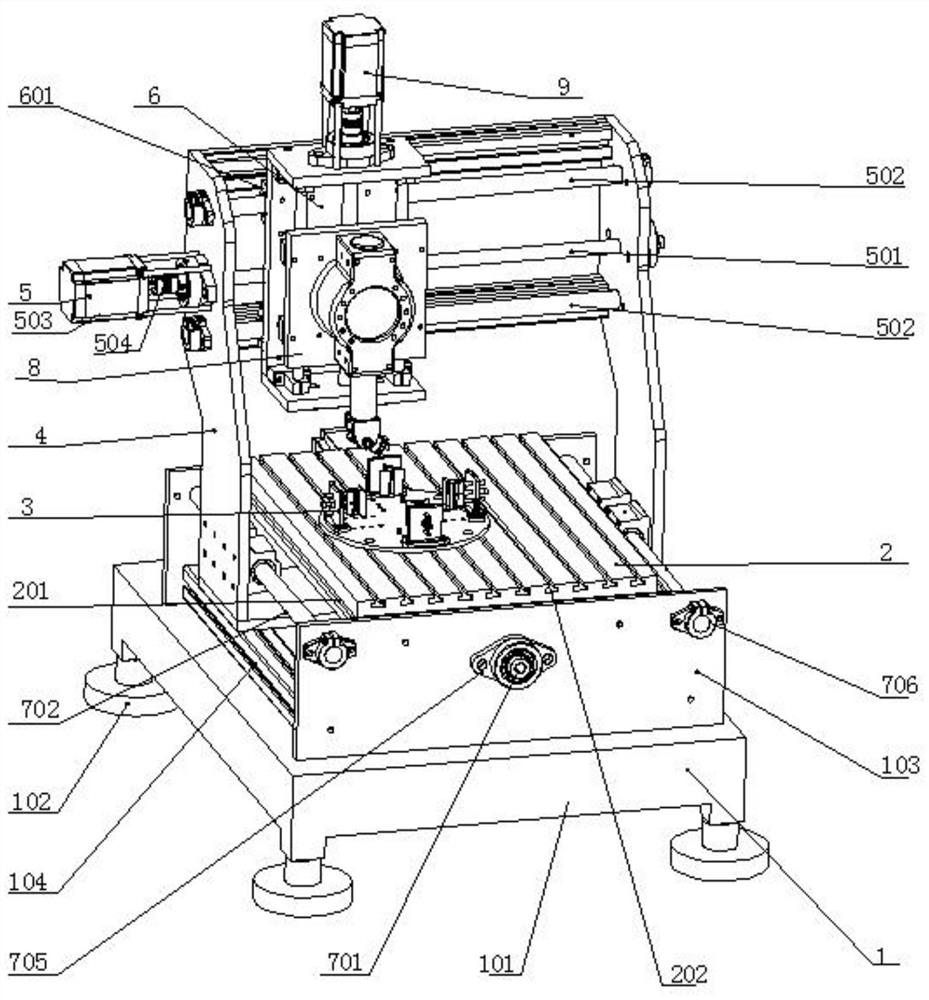
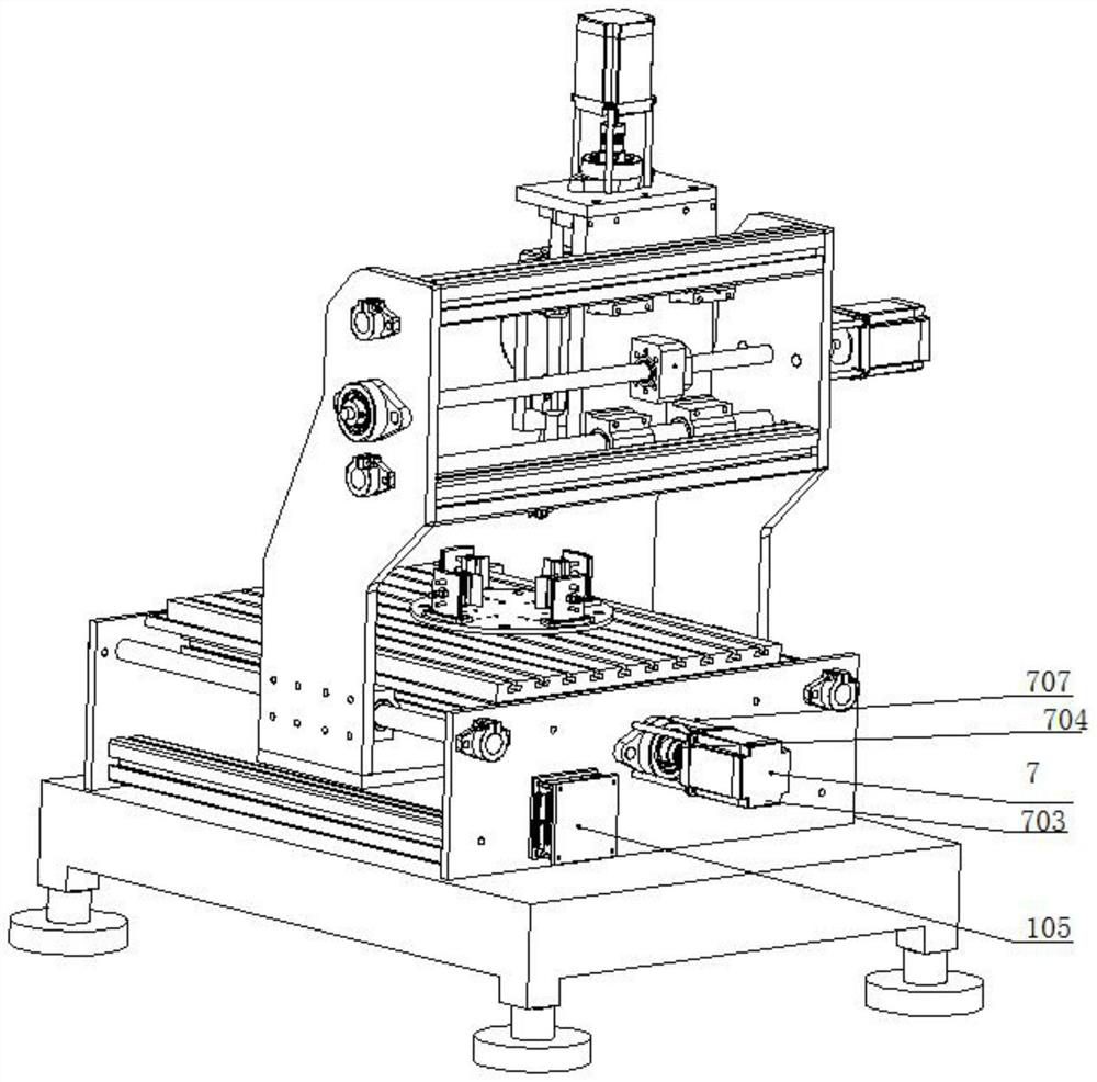
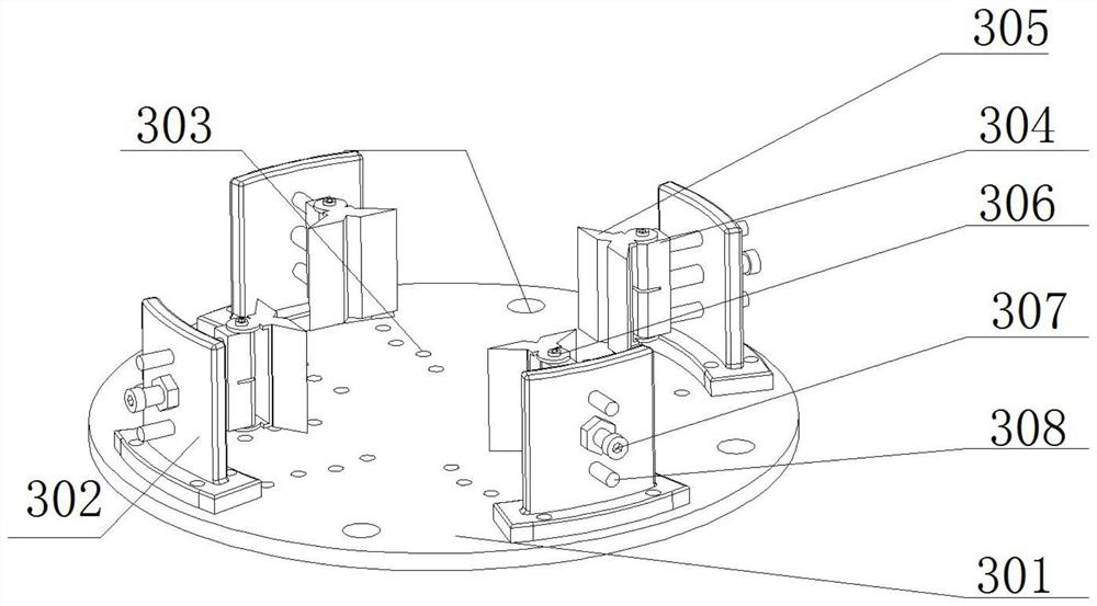
[0039] Such as Figure 1 to Figure 6 As shown, a processing device for processing an off-axis multi-reflex imaging system includes a machine tool base 1, a workbench 2 is installed on the machine tool base 1, and a workbench 2 is installed on the workbench 2 for clamping the off-axis multi-reflex imaging system. The special fixture 3 of the ...


PUM


Abstract

The invention discloses a machining device used for machining an off-axis multi-reflector imaging system. The machining device used for machining the off-axis multi-reflector imaging system comprisesa machine tool base, wherein a workbench is installed on the machine tool base, a special clamp used for clamping the off-axis multi-reflector imaging system is installed on the workbench, a moving frame is installed on the machine tool base, a lifting frame is installed in the moving frame, a lifting board is installed in the lifting frame, a rotating shaft is arranged on the lifting board, a small ultrasonic motorized spindle and a swing motor are connected with the bottom of the rotating shaft through a U-shaped board, and the small ultrasonic motorized spindle can conduct X-axis movement,Y-axis movement and Z-axis movement, and can conduct rotational movement and swing movement. During complex surface machining, complex curved surfaces can be machined by the small ultrasonic motorizedspindle which can conduct movement at multiple degrees of freedom, and the machining precision is high.

Description

technical field [0001] The invention relates to a machining device for an optical element, in particular to a machining device for machining an off-axis multi-reflection imaging system. Background technique [0002] At present, with the vigorous development of science and technology in various fields such as industry and agriculture, national defense, and aerospace, and the upgrading of industries, the application of space optical systems in agriculture and forestry, ocean monitoring, topographic mapping, military reconnaissance, resource census, and disaster prevention and rescue The application has been significantly improved. The space optical system mainly uses optical elements to image the target through multiple reflections or refractions. In various optical structures, because the reflective optical system has the characteristics of no chromatic aberration, easy optical path folding, and easy light weight, etc., in It has been widely used in space optical system. Thi...

Claims


Application Information

Patent Timeline
Patent Type & Authority Applications(China)
IPC IPC(8): B23Q1/01B23Q1/25B23Q3/06
CPCB23Q1/017B23Q1/25B23Q3/06
Inventor 孟凡伟于涛贺亚杰陈新于天彪赵继
Owner NORTHEASTERN UNIV
Learn More