Ion implantation method, preparation method of mercury cadmium telluride chip, and mercury cadmium telluride chip

A technology of ion implantation and mercury cadmium telluride, which is applied in final product manufacturing, sustainable manufacturing/processing, semiconductor/solid-state device manufacturing, etc. Effect of surface leakage current and overall performance improvement

Active Publication Date: 2021-04-13
北京智创芯源科技有限公司
View PDF15 Cites 0 Cited by
  • Summary
  • Abstract
  • Description
  • Claims
  • Application Information

AI Technical Summary

Problems solved by technology

[0004] In view of the above problems, the present disclosure provides an ion implantation method, a preparation method of a mercury cadmium telluride chip and a mercury cadmium telluride chip, which solves the serious damage of the dielectric film layer caused by the ion implantation process of the mercury cadmium telluride chip in the prior art, making Technical Problems of HgCdTe Chip Performance Deterioration

Method used


Image

  • Ion implantation method, preparation method of mercury cadmium telluride chip, and mercury cadmium telluride chip
  • Ion implantation method, preparation method of mercury cadmium telluride chip, and mercury cadmium telluride chip
  • Ion implantation method, preparation method of mercury cadmium telluride chip, and mercury cadmium telluride chip

Examples


Embodiment 1

[0044] This embodiment provides an ion implantation method. figure 2 is a schematic flowchart of an ion implantation method shown in an embodiment of the present disclosure. Figure 3-Figure 8 It is a schematic diagram of a cross-sectional structure and a front top view formed by relevant steps of an ion implantation method shown in an embodiment of the present disclosure. Below, refer to figure 2 and Figure 3-Figure 8 The detailed steps of an exemplary method of the ion implantation method proposed by the embodiments of the present disclosure will be described.

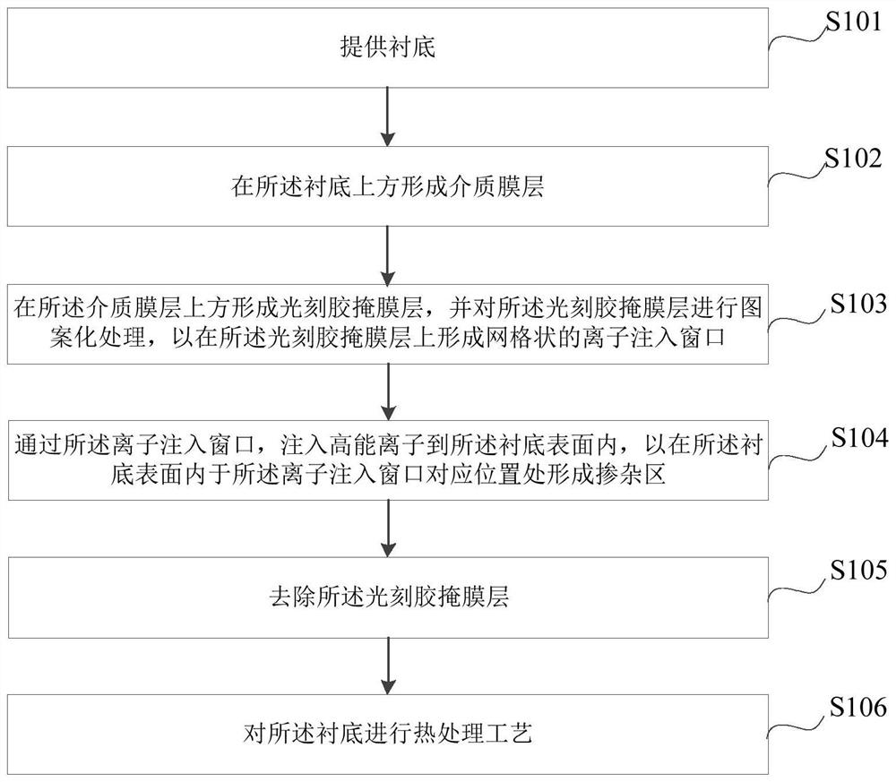
[0045] Such as figure 2 As shown, the ion implantation method of this embodiment includes the following steps:

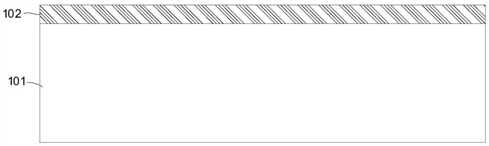
[0046] Step S101: if image 3 As shown, a substrate 101 is provided.

[0047] Step S102 : forming a dielectric film layer 102 on the substrate 101 .

[0048] In this embodiment, the dielectric film layer 102 includes at least one of SiO2, cadmium telluride and zinc sulfide.

[0049] The dielectri...

Embodiment 2

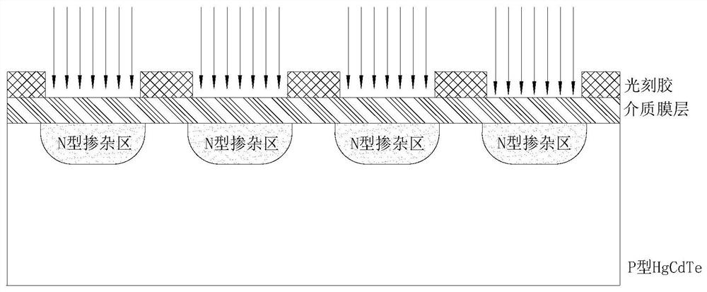
[0066] On the basis of the first embodiment, this embodiment provides a method for manufacturing a mercury cadmium telluride chip. Figure 9 It is a schematic flowchart of a method for preparing a mercury cadmium telluride chip shown in an embodiment of the present disclosure. Figure 10-Figure 16 It is a cross-sectional structure and a front top view schematic diagram formed in the relevant steps of a method for manufacturing a mercury cadmium telluride chip shown in an embodiment of the present disclosure. Below, refer to Figure 9 and Figure 10-Figure 16 The detailed steps of an exemplary method of the method for manufacturing the HgCdTe chip proposed in the embodiments of the present disclosure will be described.

[0067] Such as Figure 9 As shown, the preparation method of the mercury cadmium telluride chip of the present embodiment comprises the following steps:

[0068] Step S201: if Figure 10 As shown, a P-type HgCdTe substrate 201 is provided.

[0069] The P-...


PUM


Abstract

The disclosure provides an ion implantation method, a method for preparing a mercury cadmium telluride chip, and a mercury cadmium telluride chip. The preparation method for the mercury cadmium telluride chip includes: forming a dielectric film layer on the P-type mercury cadmium telluride substrate; The P-type mercury cadmium telluride substrate and the dielectric film layer are subjected to a heat treatment process; a photoresist mask layer is formed above the dielectric film layer, and the photoresist mask layer is patterned to A grid-shaped ion implantation window is formed on the photoresist mask layer; through the ion implantation window, high-energy ions are implanted into the surface of the P-type HgCdTe substrate, so that the P-type HgCdTe Forming an N-type doped region in the surface of the mercury substrate; removing the photoresist mask layer; performing a heat treatment process on the P-type HgCdTe substrate. This method effectively protects the dielectric film layer in the implantation region that is not bombarded by high-energy ions, and reduces the damage to the good interface formed by heat treatment between the dielectric film layer and HgCdTe.

Description

technical field [0001] The disclosure relates to the technical field of semiconductor devices, in particular to an ion implantation method, a method for preparing a mercury cadmium telluride chip, and a mercury cadmium telluride chip. Background technique [0002] Mercury cadmium telluride is an important material for preparing infrared detectors. Due to its adjustable band gap, the detection spectrum range extends from short-wave bands to very long-wave bands. It has the advantages of high photoelectric detection efficiency and is widely used in early warning detection, infrared Military and civil fields such as reconnaissance and imaging guidance. The core of the mercury cadmium telluride infrared detector chip is to use the photoelectric characteristics of the PN junction. The PN junction is usually formed by ion implantation. Ion implantation is an important means of semiconductor processing. The accelerated high-energy particles are directly injected into the material. ...

Claims


Application Information

Patent Timeline
Patent Type & Authority Patents(China)
IPC IPC(8): H01L21/426H01L21/477H01L31/18H01L31/103
CPCH01L21/426H01L21/477H01L31/1032H01L31/1832Y02P70/50
Inventor 不公告发明人
Owner 北京智创芯源科技有限公司
Why Eureka
Try Eureka