

Boiling type micro-foam soil pollution desorption device and method suitable for coking field
A soil pollution and boiling technology, applied in the field of soil remediation of polluted sites, can solve the problems of uneven foam injection, few micro-foam desorption devices, and immaturity, and achieve mild reaction conditions, avoid channel effects, and save usage. Effect
- Summary
- Abstract
- Description
- Claims
- Application Information
AI Technical Summary
Problems solved by technology
Method used
Image

Examples
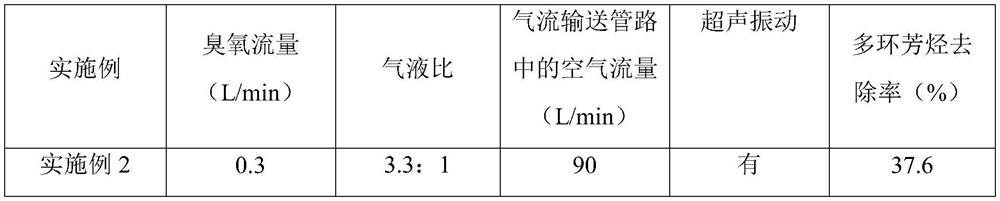
Embodiment 1
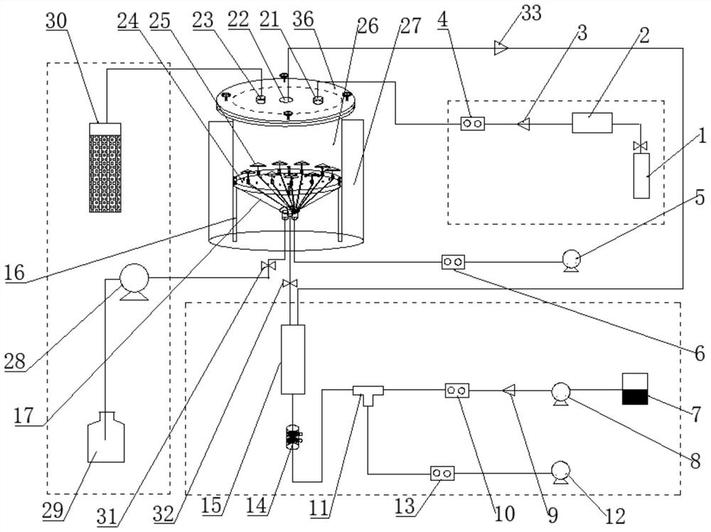
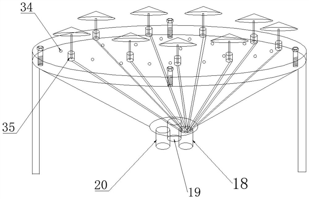
[0034] Such as figure 1 As shown, the boiling microfoam soil pollution desorption device suitable for coking sites includes a pollutant desorption device, an ozone delivery pipeline, an airflow delivery pipeline, a microfoam generation device and a waste gas and waste liquid collection device. The pollutant desorption The device comprises a chassis, the chassis is made up of a bracket 16 and a funnel-shaped groove 17 fixed at the center of the bracket, and the bottom surface of the funnel-shaped groove is provided with an airflow inlet 18, a foam inlet 19 and a waste liquid outlet 20, the airflow inlet The air outlet is provided with several small ports; the upper part of the support is provided with an elution reaction chamber 26, and the bottom of the elution reaction chamber 26 is provided with a porous support plate 24, and the porous support plate 24 is provided with several The micropore 34 is provided with an air flow branch port 35 equal in number to the small interfac...
Embodiment 2
[0041] Utilize the soil pollution desorption method of the boiling micro-foam soil pollution desorption device of the present invention, first assemble the desorption device:
[0042] ① Ozone delivery pipeline connection: connect the oxygen cylinder 1, the ozone generator 2, the first one-way valve 3, and the first flow meter 4 in sequence with a silicone tube, and connect to the ozone inlet 21;
[0043] ②Connection of the airflow delivery pipeline: connect the first air pump 5 and the second flowmeter 6 with a silicone tube, and connect with the airflow inlet 18;
[0044] ③Foam generating device connection: add the selected surfactant solution into the surfactant container 7, extend one end of the peristaltic pump 8 into the surfactant solution, and connect the second one-way valve 9 and the third flow rate with a silicone tube at the other end. Meter 10, and then connected to the first end of the tee 11; the second air pump 12 and the fourth flow meter 13 are connected to th...
Embodiment 3
[0057] The steps of the soil pollution desorption method using the boiling micro-foam soil pollution desorption device of the present invention are the same as those in Example 2, the difference is only that: the flow rate of the airflow delivery pipeline is adjusted to 120L / min, and after the desorption is completed, the high-efficiency liquid is also used Phase Chromatography (HPLC) Determination The content of polycyclic aromatic hydrocarbons in the desorbed soil was determined, and the determination parameters were set with the same as in Example 2. The test results are shown in Table 1.
PUM
 Abstract
Description
Claims
Application Information