Vacuum pumping bottle cap

A vacuum pumping and bottle cap technology, which is applied in the field of sealed bottles and cans, can solve the problems of prolonged pumping time, air entry, and inconvenient pumping, and achieve the effects of ensuring sealing effect, high pumping efficiency and simple structure

Pending Publication Date: 2020-12-18
NINGBO CHEFSHERE KITCHEN TECH
View PDF0 Cites 2 Cited by
  • Summary
  • Abstract
  • Description
  • Claims
  • Application Information

AI Technical Summary

Problems solved by technology

[0003] The existing bottle cap has a single structure, and it cannot cooperate well with external tools to extract the gas in the bottle to form a vacuum, so that the shelf life of the food in the bottle is longer
In addition, although most of the existing bottle caps adopt the technology of sealing the mouth of the bottle, in fact the sealing effect is not satisfactory. drain
[0004] Although some vacuum bottle caps have entered the market, there are still some deficiencies in the existing vacuum bottle caps, such as the existing vacuum bottle caps are not easy to disassemble with the bottle body, which reduces the convenience and convenience of cleaning. Cleanliness; the time required for vacuuming is long, and the pumping is inconvenient; the sealing of the bottle cap is low, which may easily lead to gas leakage during pumping, prolonging the pumping time, etc.

Method used


Image

  • Vacuum pumping bottle cap
  • Vacuum pumping bottle cap
  • Vacuum pumping bottle cap

Examples


Embodiment 1

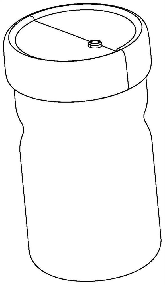
[0042] Such as Figure 1 to Figure 3 As shown, a vacuum suction bottle cap is shown, including a first cover body 1.1, a second cover body 1.2 distributed up and down and slidably connected, and an accommodating space formed by the first cover body 1.1 and the second cover body 1.2 , the accommodating space is provided with a vacuum pumping valve assembly and a pumping tool 4 communicating with the space to be pumped.

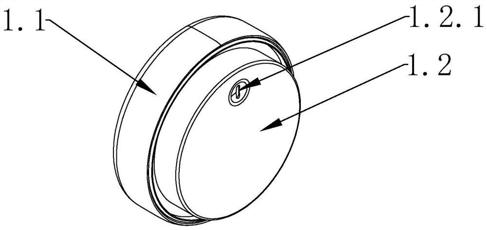
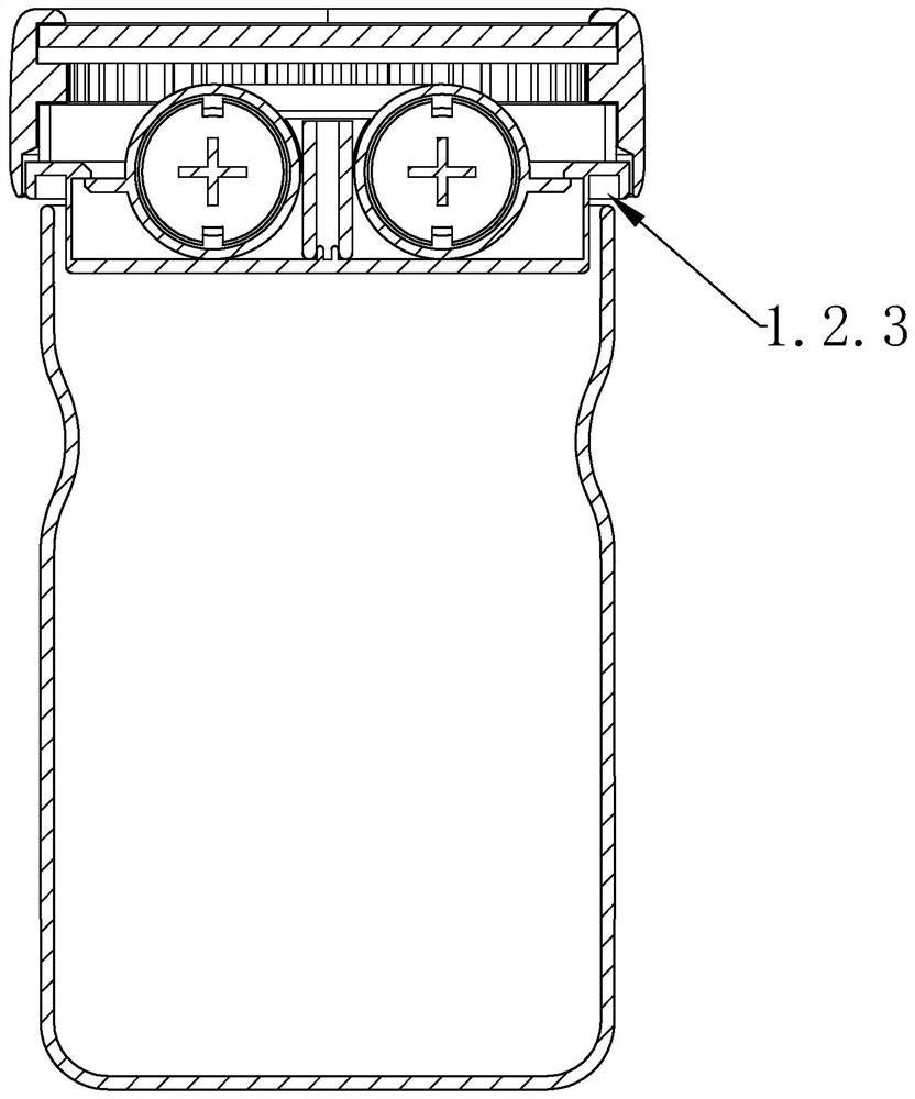
[0043] Specifically, the detachable connection between the first cover 1.1 and the second cover 1.2, in this embodiment, as image 3 As shown, the first cover 1.1 and the second cover 1.2 are mutually distributed. The second cover 1.2 is also provided with a fixed groove 1.2.3 that matches the bottle body. When in use, as long as the bottle mouth of the bottle to be pumped is connected to the fixed groove 1.2.3, the gas pumping tool The work of 4 extracts the gas from the vacuum pumping valve assembly, and ensures the vacuum sealing state through the function...

Embodiment 2

[0059] The basic structure is the same as that of Embodiment 1, the difference is that the cylinder body 4.1 can adopt double cylinders, of course, after adopting the double cylinders, the efficiency of vacuuming can be further improved, and the pumping is simpler.

[0060] The specific structural changes are as follows: Figure 4 As shown, after adopting the double bars, the same as the single cylinder also has a vacuum exhaust valve assembly, the difference is that the piston 4.2 and the piston rod 5.1 corresponding to the double cylinder in the exhaust tool 4 need to be increased. That is to say, the two cylinders 4.1 need two pistons 4.2 and two piston rods 5.1 correspondingly, and the two cylinders 4.1 are connected to each other, and the cylinders 4.1 are connected to the space to be pumped through the pumping valve core 2, Pistons 4.2 capable of reciprocating motion are respectively arranged in the two cylinders 4.1, and each piston 4.2 is respectively connected and fix...

Embodiment 3

[0062] Basic structure is identical with embodiment 2, and difference is: as Figure 8 to Figure 10 , a cam 5.6 is provided on the rotating shaft 5.3 at the bottom of the gear 5.2, and a push plate 5.7 is provided on the end of the piston rod 5.1 away from the piston 4.2. The length direction of the push plate 5.7 is perpendicular to the length direction of the piston rod 5.1, and the bottom of the push plate 5.7 A slide plate 5.8 is provided, and the length direction of the slide plate 5.8 is parallel to the length direction of the piston rod 5.1, that is to say the length direction of the slide plate 5.8 is perpendicular to the length direction of the push plate 5.7. The second cover body 1.2 is provided with a slide rail 1.2.2 matched with the slide plate 5.8, the slide plate 5.8 is provided with a first spring 5.9, and the other end of the first spring 5.9 is offset against the cylinder body 4.1 shell.

[0063]When in use, turn the first cover body 1.1, because the inner s...


PUM


Abstract

The invention discloses a vacuum pumping bottle cap. The vacuum pumping bottle cap comprises a first cap body, a second cap body and a containing space formed by the first cap body and the second capbody; the first cap body and the second cap body are distributed up and down and are connected in a sliding mode; a vacuum pumping valve assembly and a pumping tool which communicate with a space to be pumped are arranged in the containing space; the pumping tool comprises a cylinder body, a piston and a push-pull assembly; the cylinder body communicates with the vacuum pumping valve assembly; thepiston is arranged in the cylinder body and makes reciprocating motion; the push-pull assembly drives the piston to move; the cylinder body is fixed on the second cover body; and the push-pull assembly is in tooth connection with the first cover body. The bottle cap is simple in structure, good in sealing effect and capable of greatly improving the pumping efficiency.

Description

technical field [0001] The invention relates to the technical field of sealed bottles and cans, in particular to a vacuum pumping bottle cap. Background technique [0002] The bottle cap is used to seal the bottle. According to different functions and uses, there are bottle caps with different shapes and different operation methods on the market. With the improvement of people's quality of life, it is necessary to store food in airtight bottles and jars to keep fresh. Existing common fresh-keeping boxes or bottles or cans, when keeping fresh products, food storage and fresh-keeping are defined as as long as the container is well sealed, the fresh-keeping effect can be achieved. Science has proven this to be a myth. Although ordinary fresh-keeping boxes or bottles or cans have airtight properties, there is still oxygen inside, and oxygen is one of the main factors for whether they can really keep fresh. Therefore, the air in the storage tank for storing food is drawn out, ...

Claims


Application Information

Patent Timeline
Patent Type & Authority Applications(China)
IPC IPC(8): B65D51/16B65D81/20B65D51/28B65D53/02
CPCB65D51/16B65D51/28B65D53/02B65D81/2038
Inventor 张超
Owner NINGBO CHEFSHERE KITCHEN TECH
Why Eureka
Try Eureka