Environment-friendly polluted waste purification treatment device and system

A purification treatment and environmental protection technology, applied in the field of environmental purification treatment, can solve the problems of poor treatment effect, pollution of the ocean, high mechanical properties of sludge and soil, etc., and achieve the effect of easy direct use and strong versatility

Pending Publication Date: 2020-12-18
张艳
View PDF6 Cites 0 Cited by
  • Summary
  • Abstract
  • Description
  • Claims
  • Application Information

AI Technical Summary

Problems solved by technology

At present, the commonly used sludge treatment methods include: sanitary landfill, ocean dumping, recycling treatment, etc. Among them, the treatment method of sanitary landfill has high requirements on the soil mechanical properties of sludge, and requires a large area of ​​land and a large amount of transportation costs. , the foundation needs anti-seepage treatment to prevent groundwater pollution, etc. Therefore, there are high requirements and difficulties in adopting a new treatment method for the sludge; and when the ocean dumping method is used, the sludge thrown into the sea will pollute the ocean and have a negative impact on the marine ecosystem. Ocean dumping of sludge has come under increasing opposition in view of the threat it poses to the human food chain
[0004] Therefore, the current mainstream sludge treatment method is mainly recycling treatment, but the existing sludge recycling treatment has poor treatment effect during sludge treatment and cannot meet the requirements of rapid purification treatment of large quantities of sludge.

Method used


Image

  • Environment-friendly polluted waste purification treatment device and system
  • Environment-friendly polluted waste purification treatment device and system
  • Environment-friendly polluted waste purification treatment device and system

Examples


Embodiment Construction

[0030] Embodiments of the technical solutions of the present invention will be described in detail below in conjunction with the accompanying drawings.

[0031] The following examples are only used to illustrate the technical solution of the present invention more clearly, so they are only examples, and should not be used to limit the protection scope of the present invention.

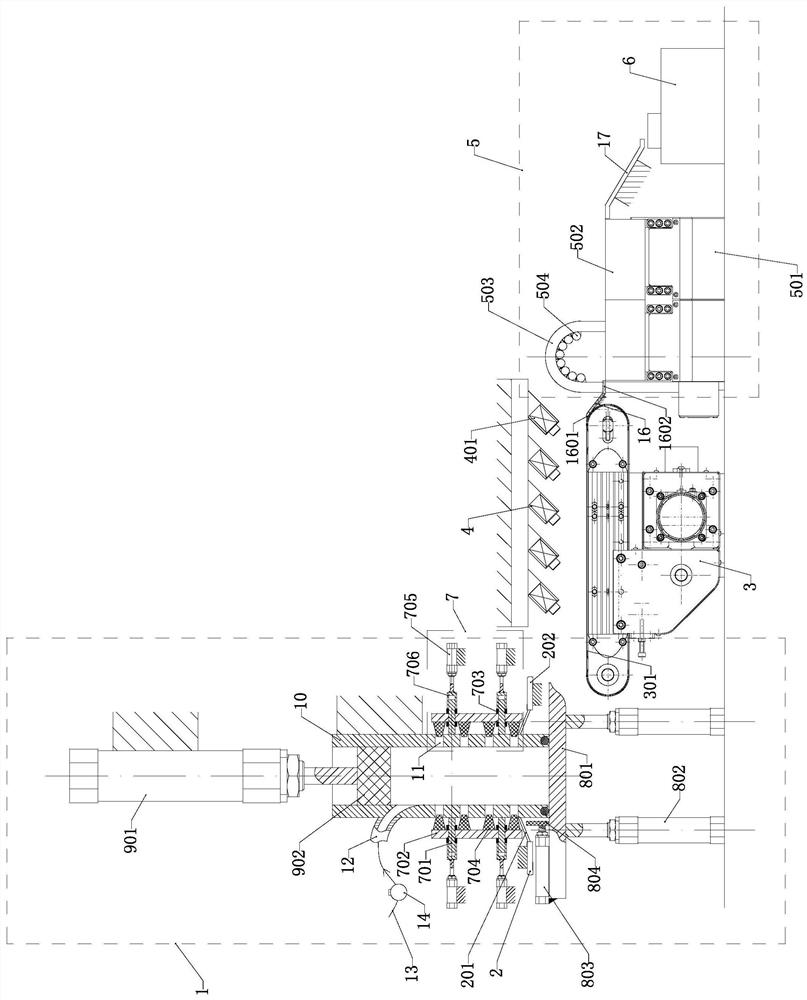
[0032] like Figure 1-4As shown in , the environment-friendly polluted waste purification treatment device includes a vertical alloy steel cylinder 10 that is vertically connected up and down. The alloy steel cylinder 10 is fixedly arranged relative to the ground, and the peripheral shape of the cross section of the alloy steel cylinder 10 is The cross-sectional shape of the inner cavity is square, and the shape of the inner cavity is circular. On the two opposite outer walls of the lower section of the alloy steel cylinder 10, there are respectively symmetrically arranged several pressurized drainage ...


PUM


Abstract

The invention relates to the technical field of environmental purification treatment, in particular to an environment-friendly polluted waste purification treatment device and system, the environment-friendly polluted waste purification treatment device comprises a vertical alloy steel cylinder arranged in an up-down penetrating mode, and a plurality of pressed drainage circular cavity channels communicated with an inner cavity of the alloy steel cylinder are symmetrically arranged on the two opposite outer side walls of the lower section of the alloy steel cylinder respectively; a gap adjusting pressure-bearing mechanism is arranged on the outer side of the outer side wall of the alloy steel cylinder provided with the pressed drainage circular cavity channels, a discharging mechanism is arranged at the bottom of the alloy steel cylinder, and a filter pressing driving part is installed in the inner cavity of the alloy steel cylinder in a matched mode. Rapid solid-liquid primary separation of water-containing sludge can be achieved through cooperation of the gap adjusting pressure-bearing mechanism and the filter pressing driving part, so that the sludge with low water content is obtained, and on-demand drying is achieved through a pneumatic drying assembly and a secondary drying assembly, so that dried organic sludge is obtained.

Description

technical field [0001] The invention relates to the technical field of environmental purification treatment, in particular to a new structure and system capable of rapid separation and treatment of sewage sludge, especially an environment-friendly pollution waste purification treatment device and system. Background technique [0002] Pollution control mainly refers to the process of improving or eliminating pollution using engineering and non-engineering methods. As my country's environmental protection work enters the stage of optimizing economic growth by protecting the environment, environmental standards are becoming an important condition for market access. Therefore, the treatment of polluted waste has also become an important indicator for considering whether the environment meets the standards. [0003] Sludge and sewage are the main components of polluted waste. If the sludge and sewage are to meet the discharge standards, they must be purified in a centralized mann...

Claims


Application Information

Patent Timeline
IPC IPC(8): C02F11/121C02F11/13
CPCC02F11/121C02F11/13
Inventor 张艳
Owner 张艳
Why Eureka
Try Eureka