
Tunnel deformation monitoring and early warning radar system

A monitoring and early warning, radar system technology, applied in radio wave measurement system, electric/magnetic solid deformation measurement, measurement device, etc., can solve the problems of increased signal error, poor real-time monitoring, short detection distance, etc., and achieve the increase of monitoring frequency , the effect of real-time monitoring

Inactive Publication Date: 2020-12-18
HUNAN TAIKANG ELECTRONICS INFORMATION TECH CO LTD
View PDF9 Cites 5 Cited by
  • Summary
  • Abstract
  • Description
  • Claims
  • Application Information

AI Technical Summary

Problems solved by technology

[0003] At present, the tunnel surrounding rock deformation monitoring technology mainly adopts artificial static inspection, such as photogrammetry, laser range finder with theodolite, total station measurement, etc. Due to inherent reasons, these methods have poor real-time monitoring and require a lot of manpower and material resources , the measurement accuracy and error are affected by many environmental factors and people's own state. The conditions in the tunnel are complex, usually accompanied by a large amount of dust, and the line of sight is extremely poor. Using this type of optical measurement method cannot work in this harsh environment.
[0004] Ultrasonic distance measurement can also be used in the field of tunnel surrounding rock deformation monitoring, but it also has obvious shortcomings. The air density and air pressure in the tunnel are not uniform, resulting in an increase in the signal error during the ultrasonic propagation process, and its attenuation in the air is large, and the detection distance nearer
Digital image processing technology is also used in the field of tunnel monitoring, but it is also greatly affected by visibility, and the cost is high

Method used


Image

  • Tunnel deformation monitoring and early warning radar system
  • Tunnel deformation monitoring and early warning radar system

Examples


Embodiment 1

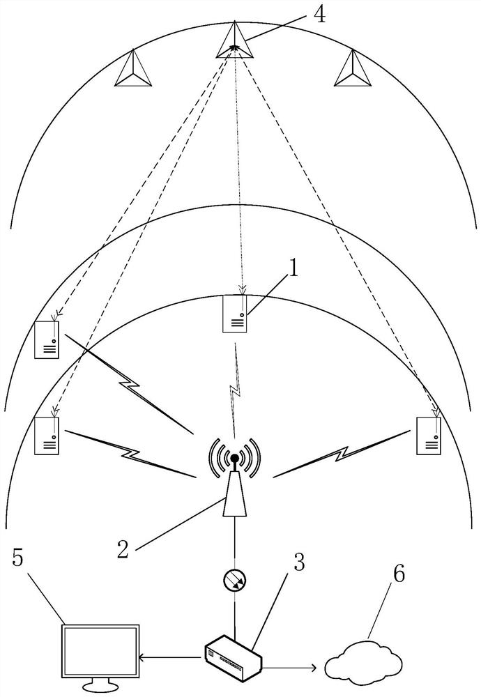
[0021] Such as Figure 1-2 As shown, a tunnel deformation monitoring and early warning radar system includes a deformation monitoring radar module 1, a router 2, a central processing unit 3, a trihedral reflector 4, an alarm system 5, and a cloud platform 6, and the deformation monitoring radar module 1 includes a radio frequency Module, radio frequency control module, communication module and signal processing module; Described central processing unit 3 comprises communication module, module control unit, data processing platform and data storage unit; Described signal processing module is used for receiving central processing unit 3 orders and to The central processing unit 3 transmits the detection signal data; the central processing unit 3 is used to analyze the received echo data and calculate the coordinates of the point to be measured according to the resolved distance information, and upload the monitoring information to the cloud platform 6 through the transmission net...

Embodiment 2

[0024] On the basis of Embodiment 1, the deformation monitoring radar module 1 is provided with at least four, which are distributed in a triangular cone type, and are used to detect the target at the point to be measured. Three of them are distributed on the same section of the tunnel, respectively located at the top of the tunnel On both sides of the tunnel, the other one is located on either side a few meters away from the previous section, and is used for range detection of targets in the direction of the radar line of sight.

Embodiment 3

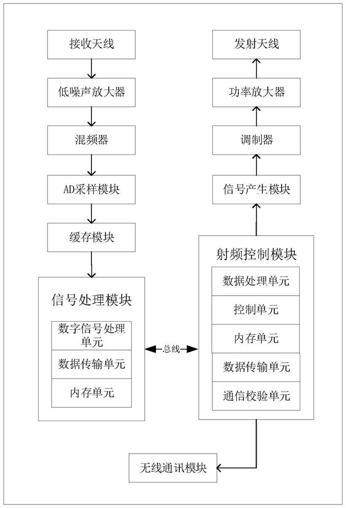
[0026] On the basis of Embodiment 1, the radio frequency module includes a signal generation module, a modulator, a power amplifier, a mixer, a low noise amplifier, an AD sampling module, a buffer module and a transceiver antenna array, and the output terminal of the signal generation module is connected to The input terminal of the modulator, the output terminal of the modulator is connected to the input terminal of the power amplifier, the output terminal of the power amplifier is connected to the input terminal of the transmitting antenna array, the signal output terminal of the receiving antenna array is connected to the input terminal of the low noise amplifier, and the output terminal of the low noise amplifier is connected to the mixer The input terminal, the output terminal of the mixer are connected to the input terminal of the intermediate frequency filter, the output terminal of the intermediate frequency filter is connected to the input terminal of the AD sampling mo...


PUM


Abstract

The invention discloses a tunnel deformation monitoring and early warning radar system, which comprises a deformation monitoring radar module, a router, a central processing unit, a trihedral corner reflector, an alarm system and a cloud platform, and is characterized in that the deformation monitoring radar module comprises a radio frequency module, a radio frequency control module, a communication module and a signal processing module; the central processing unit comprises a communication module, a module control unit, a data processing platform and a data storage unit; the signal processingmodule is used for receiving a command of the central processing unit and transmitting detection signal data to the central processing unit; the central processing unit is used for analyzing receivedecho data, calculating coordinates of a point to be measured according to the analyzed distance information, uploading monitoring information to the cloud platform through the transmission network, and completing communication, data storage, information integration and alarm system driving with the plurality of deformation monitoring radar modules; the system can work normally in various complextunnel environments, and all-weather, full-automatic and real-time monitoring, uploading and early warning can be achieved.

Description

technical field [0001] The invention relates to the technical field of tunnel surrounding rock deformation monitoring radar systems, in particular to a tunnel deformation monitoring and early warning radar system. Background technique [0002] In recent years, tunnel collapse accidents have occurred frequently, and the safety of tunnel construction and production urgently requires reliable technology to warn of possible dangerous situations; due to the complex geological conditions of construction tunnels, if encountering deformation, faults, cracks, etc., it is easy to cause geological disasters such as collapse and roof fall , thus endangering the lives of construction workers. Therefore, the monitoring and early warning of tunnel surrounding rock deformation has important theoretical significance and practical application value. [0003] At present, the tunnel surrounding rock deformation monitoring technology mainly adopts artificial static inspection, such as photogramm...

Claims


Application Information

Patent Timeline
Patent Type & Authority Applications(China)
IPC IPC(8): G01B7/16G01S13/88
CPCG01B7/16G01S13/885
Inventor 朱国富
Owner HUNAN TAIKANG ELECTRONICS INFORMATION TECH CO LTD
Learn More