Ackermann model mobile robot odometer calibration method
A mobile robot and calibration method technology, applied in the field of Ackerman model mobile robot odometer calibration, can solve the problems of assembly error, reduce the diversity of robot motion forms, low efficiency, etc., so as to eliminate the interference and motion forms of artificial ranging. The effect of diversification and improving calibration efficiency
- Summary
- Abstract
- Description
- Claims
- Application Information
AI Technical Summary
Problems solved by technology
Method used
Image

Examples
Embodiment 1
[0040] A method for calibrating the odometer of an Ackerman model mobile robot, the operation steps are as follows:
[0041] (1) Obtain the real corner of the mobile robot during motion through the IMU installed on the mobile robot;
[0042] (2) Calculate the motion speed of the mobile robot by the number of pulses per unit time of the wheel encoder, and integrate the speed to obtain the motion distance of the mobile robot within a certain time interval;
[0043] (3) According to the moving distance of the mobile robot and the rotation angle of the mobile robot obtained by the IMU, the estimated displacement of the mobile robot is obtained by using the dead reckoning algorithm;
[0044] (4) Tracking a single characteristic corner point in the environment by lidar, obtaining its distance and angle relative to the mobile robot at the two sampling times, combined with the IMU rotation angle, and using geometric derivation to calculate the real displacement of the mobile robot;
...
Embodiment 2
[0048] This embodiment is basically the same as Embodiment 1, and the special features are as follows:
[0049]In the present embodiment, in the step (3), the steps of obtaining the estimated displacement of the mobile robot are as follows:
[0050] (3-1) Get the motor speed ω m , then the moving linear velocity of the mobile robot body is v c =r·ω m ; where r is the wheel radius of the mobile robot;
[0051] (3-2) Integrate the speed of the mobile robot to obtain the movement distance s in a given time interval;
[0052] (3-3) Take the midpoint of the connection line between the rear wheels of the mobile robot as the reference point O, and move the reference point from A(x, y) to B(x', y') around point O;
[0053] (3-4) According to the dead reckoning algorithm: Where s is the moving distance of the car within a given time, θ 1 ,θ 2 are the attitude angles of the car during the two sampling times;
[0054] (3-5) Calculate the displacement of the mobile robot based on...
Embodiment 3
[0067] This embodiment is basically the same as the above-mentioned embodiment, and the special features are as follows:
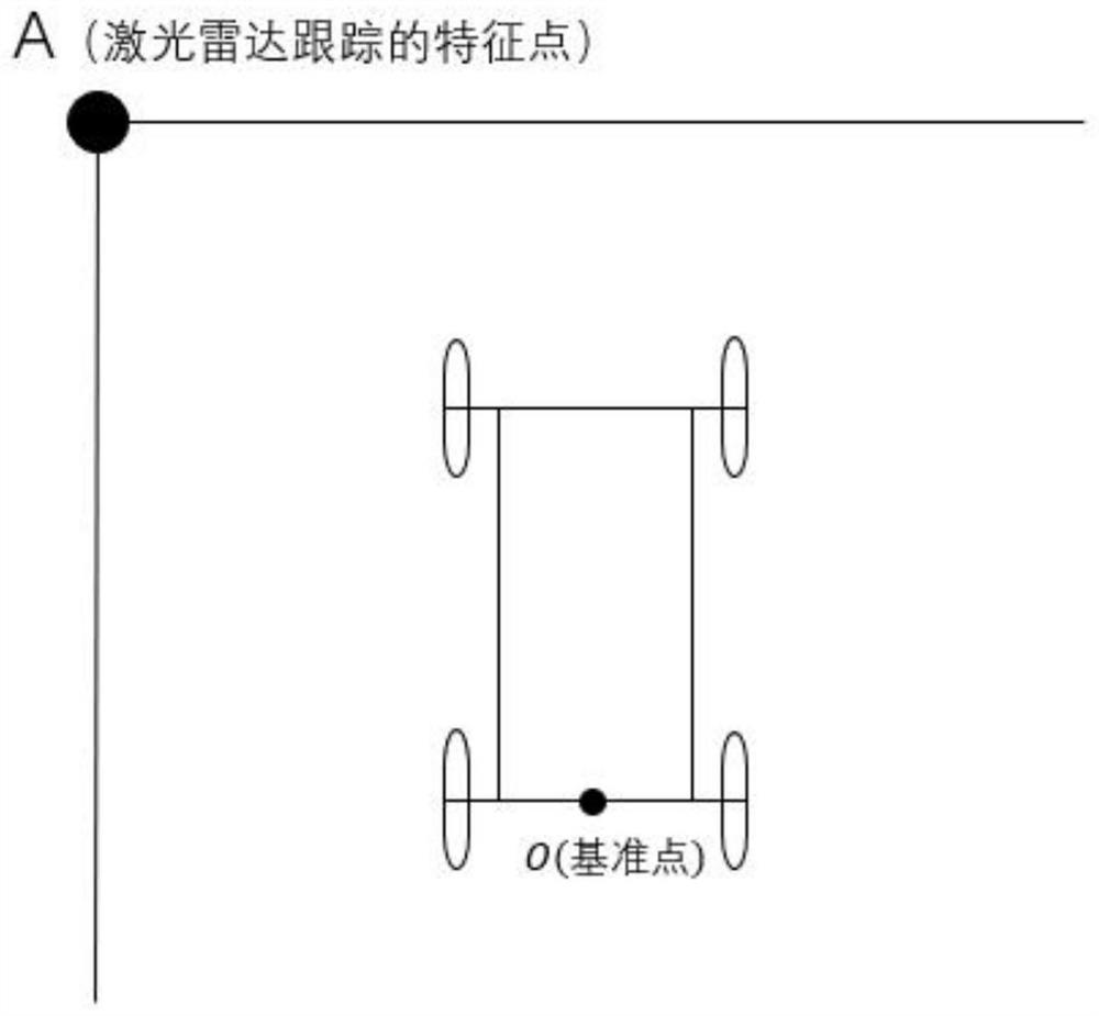
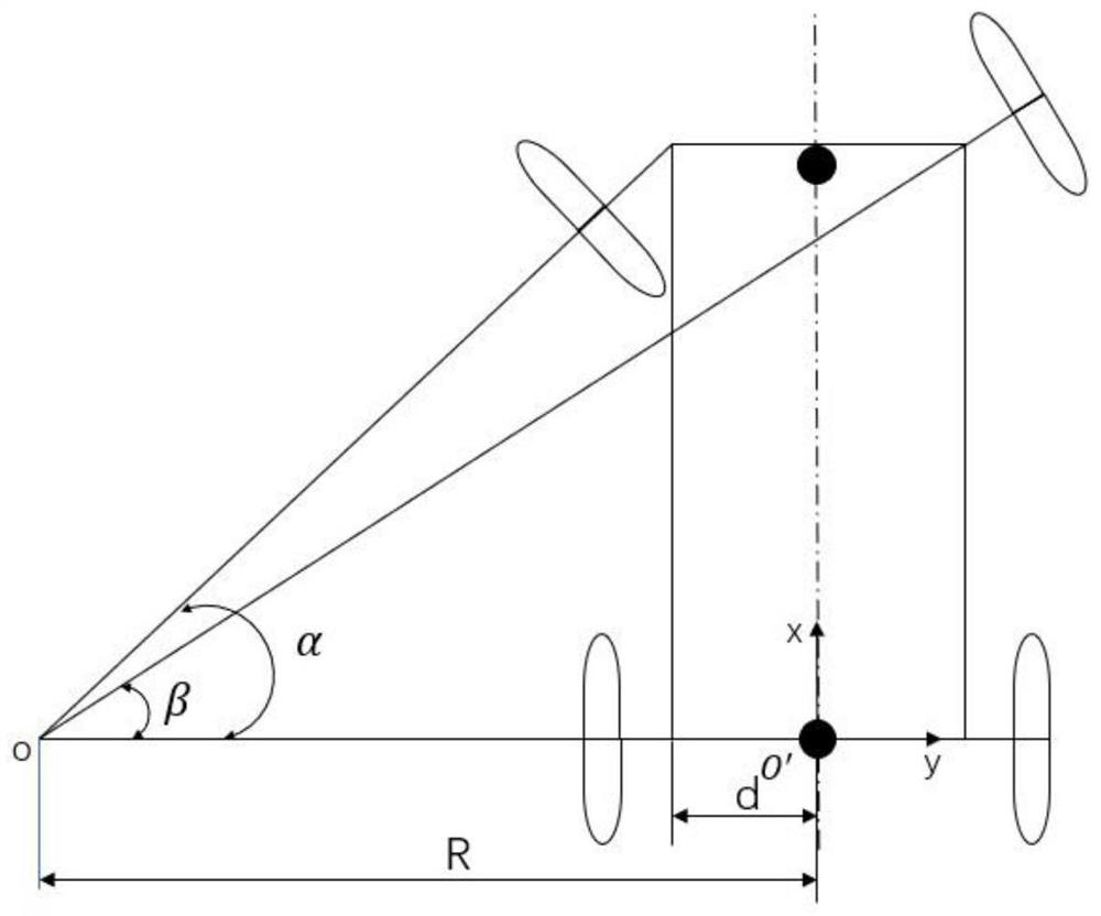
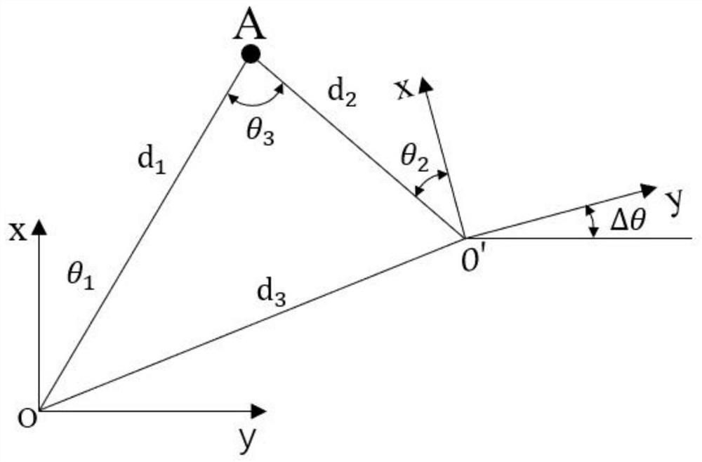
[0068] In this example, figure 1 Is the schematic diagram of the mobile robot motion environment. It is required that in this environment, there is only one corner point within the detectable range of the lidar for the lidar to track. figure 2 It is the dynamic model of the Ackerman model mobile robot. The lidar and IMU can be installed on the head and tail of the robot along the central axis of the robot. image 3 It is a schematic diagram of the laser measuring the displacement of the mobile robot. According to the two sampling, the displacement of the mobile robot is estimated. Figure 4 It is a schematic diagram of the dead reckoning of the Ackerman model mobile robot. Using the encoder and IMU information, the pose of the mobile robot at the two sampling times is estimated. Figure 5 It is the data processing flow of the odometer calibration of th...
PUM
 Abstract
Description
Claims
Application Information