
Detection system and method for main transformer oil level temperature measurement equipment

A temperature measurement and detection system technology, which is applied in the detection field, can solve the problems of display temperature display temperature difference, false alarm signal, single temperature abnormality, etc., and achieve the effect of reducing operation time, reducing the pressure of personnel tension, and high accuracy

Active Publication Date: 2020-12-18
STATE GRID SHANDONG ELECTRIC POWER +1
View PDF6 Cites 0 Cited by
  • Summary
  • Abstract
  • Description
  • Claims
  • Application Information

AI Technical Summary

Problems solved by technology

[0004] The inventor found in the actual operation that due to the harsh environment of the main transformer oil level thermometer and the secondary circuit, various defects often occur. Common defects include: on-site instrument panel display temperature, temperature gauge transmitter and Dispatch monitoring shows that there is a difference between the three temperatures, or a single temperature is abnormal, and the alarm signal, trip command, control air cooling and other information are sent by mistake
The work involved in the main transformer oil temperature gauge and its secondary circuit is very complicated, and the tools and methods available on site are very limited. According to the existing inspection methods, it will generate a huge workload, the work quality is not high, and the work efficiency is low. cause waste of manpower and material resources

Method used


Image

  • Detection system and method for main transformer oil level temperature measurement equipment
  • Detection system and method for main transformer oil level temperature measurement equipment
  • Detection system and method for main transformer oil level temperature measurement equipment

Examples


Embodiment Construction

[0025] It should be noted that the following detailed description is exemplary and intended to provide further explanation of the present disclosure. Unless defined otherwise, all technical and scientific terms used herein have the same meaning as commonly understood by one of ordinary skill in the art to which this disclosure belongs.

[0026] It should be noted that the terminology used herein is only for describing specific embodiments, and is not intended to limit the exemplary embodiments according to the present disclosure. As used herein, unless the context clearly dictates otherwise, the singular is intended to include the plural, and it should also be understood that when the terms "comprising" and / or "comprising" are used in this specification, they mean There are features, steps, operations, means, components and / or combinations thereof.

[0027] In the case of no conflict, the embodiments in the present disclosure and the features in the embodiments can be combine...


PUM


Abstract

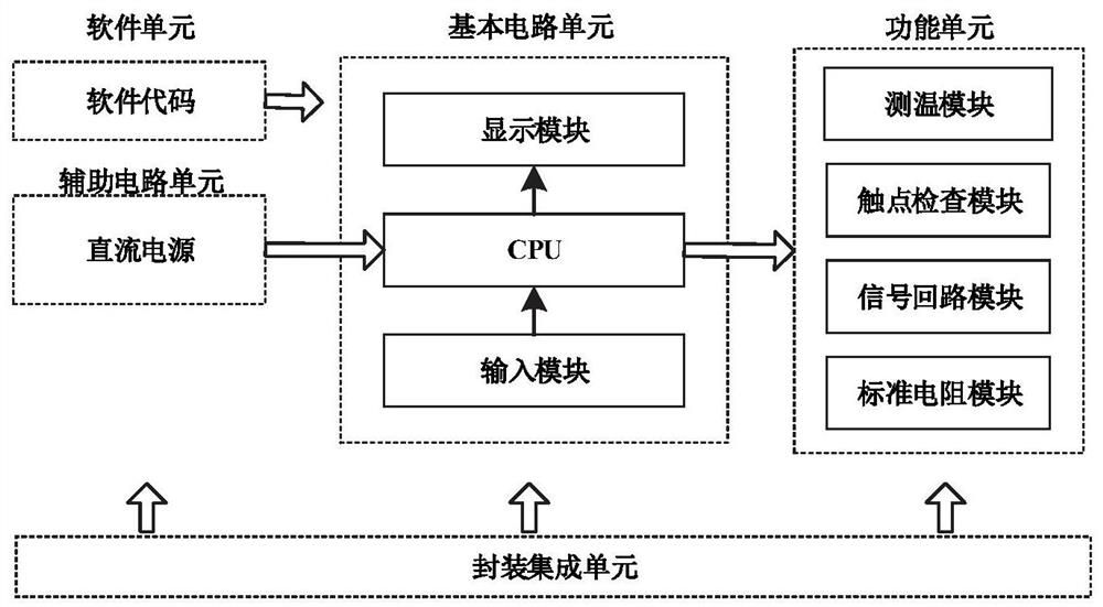
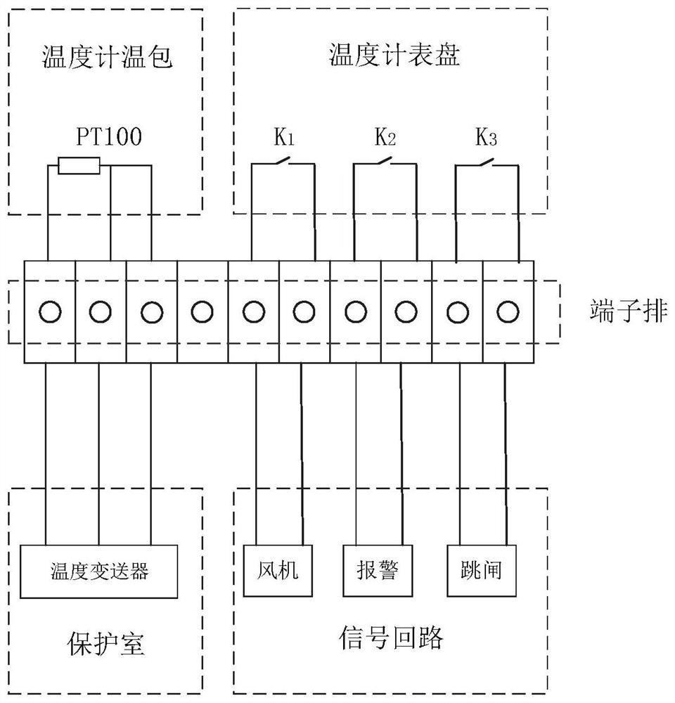
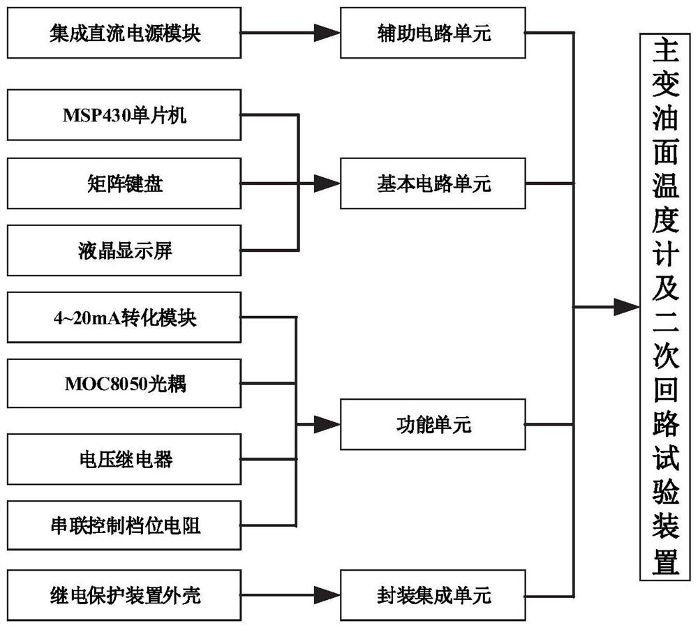
The invention provides a detection system and method for main transformer oil level temperature measurement equipment; and the system comprises a detection unit and a processor. The detection unit isused for detecting the working states of a main transformer oil level thermometer and a secondary loop of the main transformer oil level temperature measurement equipment, and the secondary loop is divided into a plurality of sub-loops according to the functions of the secondary loop, each sub-loop and the main transformer oil level thermometer are respectively connected to the respective corresponding detection unit; and the processor is used for receiving the working state signals of the main transformer oil level thermometer and the secondary circuit detected by the detection unit, judgingwhether the main transformer oil level thermometer and the secondary loop have faults or not and locating fault parts. Comprehensive inspection of a main transformer oil level thermometer and a secondary loop can be achieved, the efficiency and quality of acceptance, regular inspection and defect elimination work of the main transformer oil level thermometer and the secondary loop are improved, and safe and stable operation of a main transformer is guaranteed.

Description

technical field [0001] The disclosure belongs to the technical field of detection, and in particular relates to a detection system and method of a main transformer oil surface temperature measuring device. Background technique [0002] The statements in this section merely provide background information related to the present disclosure and do not necessarily constitute prior art. [0003] The main transformer oil level temperature measuring equipment includes an oil level thermometer, which is a kind of temperature measuring instrument, and usually consists of a pressure instrument thermometer and a thermal resistance to realize the local indication and remote display of the measured temperature. The oil level thermometer is used to measure the oil temperature of the upper layer of the transformer oil tank, monitor whether the transformer is running normally, and prevent the transformer oil temperature from being too high and accelerate the aging of the transformer. The th...

Claims


Application Information

Patent Timeline
Patent Type & Authority Applications(China)
IPC IPC(8): G01K7/20G01K15/00G01R31/00
CPCG01K7/20G01K15/007G01R31/00
Inventor 韩兴磊马晓路李峰刘烨刘嘉超张弘石峥文宏成闫新宫邦润
Owner STATE GRID SHANDONG ELECTRIC POWER
Learn More