
Microfluidic switch based on photophoresis effect

A photophoretic and switching technology, which is applied in the coupling of optical waveguides, optics, light guides, etc., can solve the problems of no combination work, the inability to achieve stable and controllable operation of absorbing particles, and no microfluidic combination. It achieves a compact structure, Effects that are conducive to miniaturization and integration

Active Publication Date: 2020-12-18
HARBIN ENG UNIV
View PDF5 Cites 1 Cited by
  • Summary
  • Abstract
  • Description
  • Claims
  • Application Information

AI Technical Summary

Problems solved by technology

[0004] Patent CN109300570B discloses a light-driven vibration device based on optical fiber, which utilizes the effects of two kinds of photophoretic forces to realize the stable control of the absorbing particles, realize the control of the vibration frequency of the absorbing particles, and simplify the light-driven motor device, but this light-driven Vibration device, unable to achieve stable and controllable operation of absorbent particles, nor integrated with microfluidics
[0005] Some recent studies have shown that the capture and manipulation of strongly absorbing particles can be achieved by using the photophoretic effect. The absorbing particles absorb light to generate a temperature gradient on the particle surface, and the absorbing particles that generate a temperature gradient on the particle surface exchange heat with the surrounding liquid environment. When introducing photophoretic force, Y. Zhang (Optics Express, 27(9), 12414, 2019) et al. proposed the attraction of strongly absorbing particles in liquids, and used Gaussian beams and Bessel beams to realize the attraction of absorbing particles in a glycerol environment. However, this kind of optical fiber optical tweezers using photophoretic effect focuses on the research on the capture and operation of particles by photophoretic force, and there is no work in combination with microfluidics.

Method used


Image

  • Microfluidic switch based on photophoresis effect
  • Microfluidic switch based on photophoresis effect
  • Microfluidic switch based on photophoresis effect

Examples


Embodiment Construction

[0017] The present invention will be further described in detail below in conjunction with the accompanying drawings and specific embodiments.

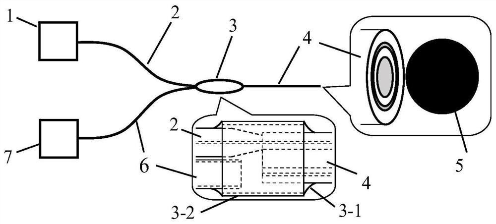
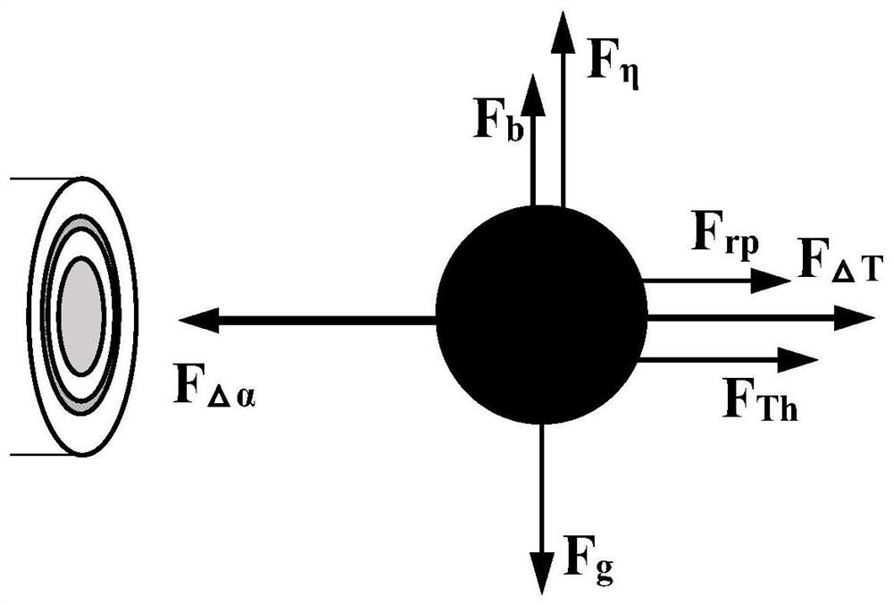
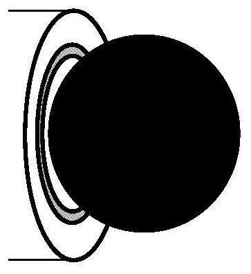
[0018] to combine Figure 1 to Figure 3 , The photophoretic effect-based microfluidic switch of the present invention includes a laser 1 , a transmission fiber 2 , a microfluidic laser coupling device 3 , a holey optical fiber 4 , absorbing particles 5 , a microfluidic conduit 6 , and a microinjection pump 7 . The laser 1 is pigtailed and connected to the transmission fiber 2 through the microfluidic laser coupling device 3 to couple the laser light into the core of the optical fiber with a hole 4, and after being transmitted through the optical fiber with a hole 4, it acts on the absorptive particles 5 at the output port of the microfluidic channel, The microfluid pumped out by the microinjection pump 7 is pumped into the optical fiber hole 4 through the microfluidic catheter 6 through the microfluidic laser coupling device 3 to form...


PUM

PropertyMeasurementUnit
lengthaaaaaaaaaa

Abstract

According to the microfluidic switch based on the photophoresis effect, the positions of the absorptive particles are controlled through the photophoresis force borne by the absorptive particles in liquid, and the function of opening and closing a microfluidic channel is achieved. According to the optical fiber microfluid switch based on the photophoresis effect, the photophoresis force for controlling the absorptive particles is determined by heat exchange between the particles and surrounding media, and the optical fiber microfluid switch comprises a laser device, a transmission optical fiber, a microfluid laser coupling device, an optical fiber with a hole, the absorptive particles, a microfluid guide pipe and a microinjection pump. According to the invention, the photophoresis effect of the absorptive particles is utilized to achieve the light-operated microfluidic switch, the opening and closing of the microfluidic channel can be flexibly controlled on line in real time, and the microfluidic switch is simple in structure, easy to realize integration, low in cost and convenient to operate.

Description

technical field [0001] The invention relates to a photophoretic effect-based microfluidic switch, which belongs to the technical field of microfluidic control. Background technique [0002] Microfluidic control technology refers to the technology of controlling the flow, mass transfer and heat transfer of fluids with volumes from picoliters to nanoliters in at least one low-dimensional channel structure with a dimension of micron or even nanometer scale. It can be widely used in biochemical analysis, immune Analysis, minimally invasive surgery, environmental monitoring and many other fields. The key technologies of microfluidic control mainly include: the design and manufacture of microchannel structures, the drive and control of micro-nano-scale fluids, and the integration and packaging of microfluidic control devices and systems. The design and manufacture of microchannel structures and the driving and control of micro-nanoscale fluids are the premise of microfluidic cont...

Claims


Application Information

Patent Timeline
Patent Type & Authority Applications(China)
IPC IPC(8): G02B6/35
CPCG02B6/354
Inventor 张亚勋汤晓云刘志海张羽杨军苑立波
Owner HARBIN ENG UNIV
Learn More