Inter-harmonic oscillation suppression method and device for grid-connected converter

A harmonic oscillation and converter technology, applied in harmonic reduction devices, AC networks to reduce harmonics/ripples, circuit devices, etc., can solve the induced system, output harmonic current amplitude amplification, system forced Vibration and other problems, to achieve good suppression effect, the effect of amplitude reduction

Active Publication Date: 2020-12-18
STATE GRID HENAN ELECTRIC POWER ELECTRIC POWER SCI RES INST +1
View PDF6 Cites 4 Cited by
  • Summary
  • Abstract
  • Description
  • Claims
  • Application Information

AI Technical Summary

Problems solved by technology

[0004] The low-frequency inter-harmonic voltage of the system will cause continuous periodic fluctuations in the output active power of the grid-connected converter. Interharmonic current amplitude amplification, thus inducing system oscillation

Method used


Image

  • Inter-harmonic oscillation suppression method and device for grid-connected converter
  • Inter-harmonic oscillation suppression method and device for grid-connected converter
  • Inter-harmonic oscillation suppression method and device for grid-connected converter

Examples


Embodiment 1

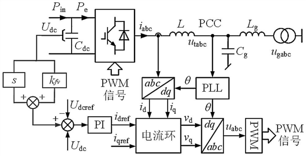
[0040] This embodiment provides a method for suppressing harmonic oscillation between grid-connected converters, such as figure 1 shown, including:

[0041] Step 1: collect the AC current at the AC output terminal of the grid-connected inverter, and convert the AC current in the three-phase static coordinate system to the two-phase rotating coordinate system through coordinate transformation according to the output phase θ of the phase-locked loop at the grid-connected point current vector i d i q .

[0042] figure 1 Shown is the grid-connected converter control block diagram of the embodiment of the present invention, P in Indicates the power input by the main front end of the converter, which can be wind turbine, photovoltaic or direct current transmission. P e is the output power of the converter, u tabc is the grid-connected point voltage, u gabc is the system voltage; L is the filter inductance of the converter, L g and C g are the equivalent inductance and capa...

Embodiment 2

[0061] This embodiment provides a harmonic oscillation suppression device for grid-connected converters, including:

[0062] The first coordinate conversion module is used to collect the AC current at the AC output terminal of the grid-connected inverter, and convert the AC current in the three-phase static coordinate system to two-phase through coordinate transformation according to the output phase θ of the phase-locked loop of the grid-connected point The current vector i in the rotating coordinate system d i q ;

[0063] The PD regulation module is used to collect the DC voltage at the DC input terminal of the grid-connected converter, output the DC voltage after the PD regulation, and use the DC voltage output after the PD regulation as the feedforward of the d-axis DC voltage loop;

[0064] The d-axis current loop module is used for the difference between the DC voltage output by the PD after adjustment and the given value of the DC voltage, through the PI controller, ...


PUM


Abstract

The invention relates to an inter-harmonic oscillation suppression method and device for a grid-connected converter. The method comprises the steps of collecting the direct-current voltage of a direct-current input end of the grid-connected converter, outputting the direct-current voltage of the grid-connected converter through a differential link, and amplifying the direct-current voltage outputted by the differential link through a proportional link; and feeding forward the differential proportional amplification value of the direct-current voltage to an instruction value of the direct-current voltage so as to suppress inter-harmonic-induced grid-connected converter oscillation. According to the invention, by setting the differential proportion feedforward mode, the converter oscillationinduced by the inter-harmonics can be well suppressed, so that the amplitude of the system oscillation is greatly reduced.

Description

technical field [0001] The application belongs to the technical field of power electronic equipment, and in particular relates to a method for suppressing inter-harmonic oscillation of grid-connected converters. Background technique [0002] With the rapid development of new energy grid-connected power generation, flexible DC transmission and dynamic reactive power compensation and other applications, the penetration rate of power electronic converters in power systems is getting higher and higher. With the rapid development of modern industry and the increasing non-linear power load, a large number of inter-harmonics appear in the grid voltage. Therefore, the oscillation problem of grid-connected converters caused by inter-harmonics cannot be ignored. The problems caused by the interharmonics in the system are becoming more and more prominent, and the pollution and harm to the power grid are showing an increasingly serious trend. Compared with the traditional power system ...

Claims


Application Information

Patent Timeline
Patent Type & Authority Applications(China)
IPC IPC(8): H02J3/24H02J3/38H02J3/01
CPCH02J3/241H02J3/38H02J3/01Y02E40/40
Inventor 肖寒潘勇卢梦瑶李强刘莘昱耿进锋朱全胜赵理沈蒙余攀
Owner STATE GRID HENAN ELECTRIC POWER ELECTRIC POWER SCI RES INST
Why Eureka
Try Eureka