Bilateral feedback control method and bilateral feedback device

A feedback control, bilateral technology, applied in the control/regulation system, output power conversion device, adjustment of electrical variables, etc., can solve the problem of burning the secondary circuit synchronous switch tube, the optocoupler current limiting resistance can not be too large, unable to stabilize Work and other issues to achieve the effect of improving dynamic response, reducing no-load power consumption, and reducing power consumption

Active Publication Date: 2020-12-18
SHENZHEN YUANNENG ELECTRIC CO LTD
View PDF6 Cites 2 Cited by
  • Summary
  • Abstract
  • Description
  • Claims
  • Application Information

AI Technical Summary

Problems solved by technology

When the constant power mode is adopted, when the voltage becomes smaller, the output current will increase correspondingly, then the synchronous switch tube in the secondary circuit will be burned out due to the excessive current.
In addition, since the SSR architecture requires real-time feedback from the optocoupler, especially in the power adapter PD, the optocoupler current-limiting resistor should not be too large, otherwise it will not work stably. If it is too small, there will be problems such as high no-load power consumption.

Method used


Image

  • Bilateral feedback control method and bilateral feedback device
  • Bilateral feedback control method and bilateral feedback device
  • Bilateral feedback control method and bilateral feedback device

Examples


Embodiment 1

[0073] Please refer to Figure 5 , this embodiment proposes a logic control method for bilateral feedback, which can be applied to the above-mentioned bilateral feedback architecture DSR, and the method includes:

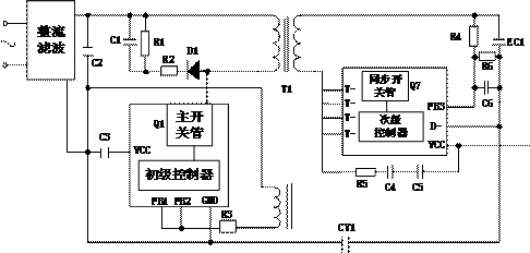
[0074] S110, the primary controller judges the timing stage of the circuit according to the voltage change on the transformer winding.

[0075] Exemplarily, with figure 1 Taking the bilateral feedback architecture shown as an example, the primary controller can obtain the voltage change of the transformer by collecting the voltage signal on the winding on the primary side of the transformer in real time. Furthermore, the primary controller performs circuit sequence judgment according to the voltage change signal, so as to know which stage the transformer sequence is currently in.

[0076] It can be understood that no matter whether it is the main switching tube Q1 or the synchronous switching tube Q7, as long as the switching tube is turned on or off, the magnetic...

Embodiment 2

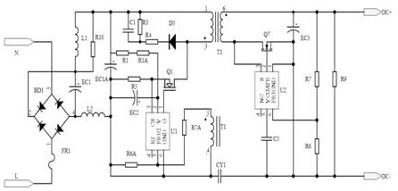
[0127] Please refer to Figure 13 and Figure 14 , this embodiment also proposes a bilateral feedback logic control method, which is applied to the above-mentioned bilateral feedback architecture. The difference from Embodiment 1 is that the bilateral feedback control method of this embodiment is mainly based on the voltage change signal of the secondary circuit The primary reference voltage (the reference voltage of FB1 / FB2) in the primary circuit loop is adjusted, so as to realize the control of the main switching tube. This method can realize variable voltage output, especially fast response in technologies such as fast charging.

[0128] Exemplarily, after power-on, the primary controller controls the bilateral feedback architecture to enter the primary feedback control mode to establish the initial operating voltage required by the circuit, and after the initial operating voltage is established, the secondary controller passes the secondary feedback terminal Obtain the ou...

Embodiment 3

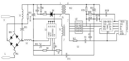
[0145] Please refer to figure 1 , this embodiment proposes a bilateral feedback device, exemplary, such as figure 2 As shown, the bilateral feedback device can adopt the method of the above-mentioned embodiment 1 or 2 for circuit logic control. Optionally, as in image 3 As shown, the bilateral feedback device also includes a fast charging circuit connected to the secondary output. At this time, the secondary circuit needs to meet the variable voltage output function. Among them, the fast charging circuit will support the fast charging protocol. If the fast charging mode is required, the secondary controller of the secondary circuit can change the voltage to meet the voltage or current required for fast charging; if the non-fast charging mode is used , then the secondary circuit can also step down to normal charging mode and so on. In one embodiment, the fast charging circuit can be integrated in the same chip with devices such as the primary controller and the synchronous...


PUM


Abstract

The embodiment of the invention provides a bilateral feedback control method and a bilateral feedback device. The bilateral feedback control method is applied to a bilateral feedback architecture, andthe method comprises the following steps: judging the time sequence stage of a circuit according to the voltage change on a transformer winding, and when a feedback signal of a secondary circuit is detected, enabling the primary controller to control the main switching tube according to the current time sequence stage when the feedback signal is detected and the feedback voltage change signal ofthe secondary circuit. A bilateral feedback logic control method is adopted for a bilateral feedback architecture, secondary output ripples can be reduced, dynamic response and no-load power consumption are improved, the power consumption of a main switching tube during switching-on is reduced, and EMI is improved; and variable voltage output and the like can be realized.

Description

technical field [0001] The present application relates to the technical field of power supplies, and in particular to a bilateral feedback control method and a bilateral feedback device. Background technique [0002] In the primary side feedback architecture (PSR), the secondary voltage change can only be monitored when the secondary is demagnetized, so it needs to be lightly turned on every preset time (usually 0.5ms~5ms) in the no-load state , for the energy transferred frequently, it needs to use the secondary dummy load to discharge, which will increase the no-load power consumption of the whole circuit. Not only that, when the no-load suddenly becomes full-load, it needs to wait until the next cycle to feed back to the primary circuit, causing the output voltage of the secondary circuit to drop rapidly, which means that the dynamic response of the circuit is poor. In the secondary side feedback architecture (SSR), since the feedback terminal is composed of optocoupler,...

Claims


Application Information

Patent Timeline
Patent Type & Authority Applications(China)
IPC IPC(8): H02M3/335
CPCH02M3/33592H02M1/0016H02M1/0035Y02B70/10
Inventor 严宗周
Owner SHENZHEN YUANNENG ELECTRIC CO LTD
Why Eureka
Try Eureka