Multi-layer gas storage tank device and gas storage method
A gas storage tank, multi-layer technology, which is applied in the field of gas collection, can solve the problems of inconvenient operation, low sampling efficiency, and large number of gas storage tanks, and achieves the effects of convenient transportation, operation, and convenient release.
- Summary
- Abstract
- Description
- Claims
- Application Information
AI Technical Summary
Problems solved by technology
Method used
Image

Examples
Embodiment 1
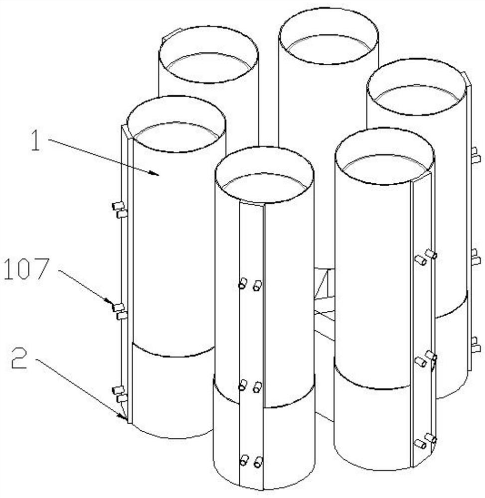
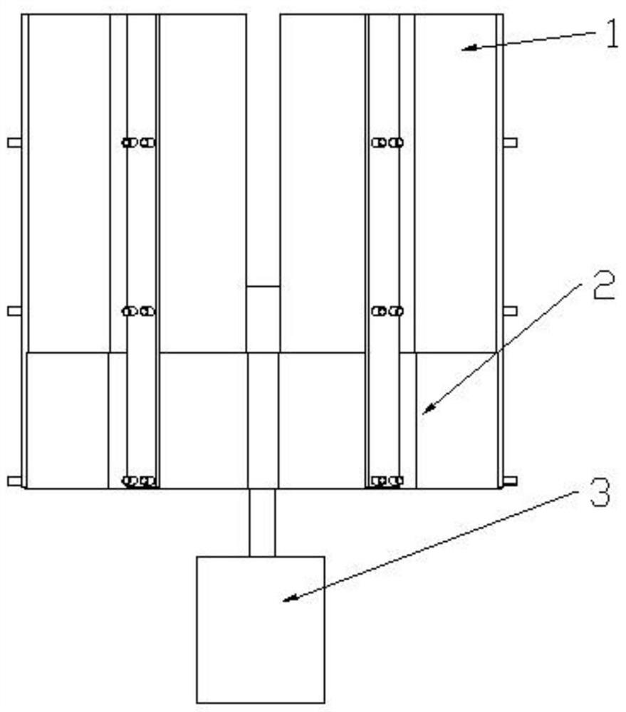
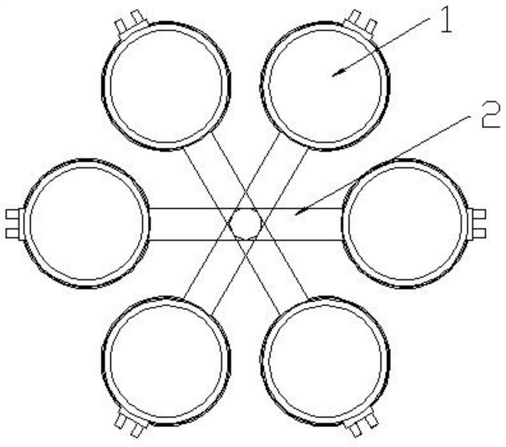
[0037] Such as Figure 1-4 As shown, the present embodiment proposes a multi-layer gas storage tank device, including a fixed seat 2, a plurality of gas storage tanks 1 are fixedly connected to the fixed seat 2, six gas storage tanks 1 can be provided, and the gas storage tanks The tank 1 forms a circle, which facilitates the movement of the gas storage tank 1 and the gas storage work. The central axis of the fixed seat 2 is fixedly connected with the first motor 3, the first motor 3 is used to drive the fixed seat 2 to rotate, and the first motor 3 is connected with the controller; when the gas storage tank 1 has stored the gas, the first motor 3 drives The fixed seat 2 rotates, and the gas storage tank 1 that has completed the gas storage is rotated to another position, and the new gas storage tank 1 is rotated to the gas storage position, thereby starting a new round of gas storage work.
[0038] The third piston 103, the second piston 102 and the first piston 101 are slid...
Embodiment 2
[0050] Such as Figure 5-6 As shown, the present embodiment proposes an automatic air collection device, including a vertically placed fixed plate 4, one side of the fixed plate 4 is provided with a horizontal movement plate 13, and the bottom end of the horizontal movement plate 13 is connected with a displacement mechanism, and the displacement mechanism is used To drive the horizontal movement plate 13 to move left and right; the displacement mechanism is connected to the fixed plate 4 through the lifting mechanism, and the lifting mechanism is used to drive the displacement machine to move up and down;
[0051] The horizontal motion plate 13 is fixedly connected with the second cylinder 14 through the large cylinder fixing seat 15, and the horizontal motion plate 13 is also fixedly connected with an air storage box 17, and the air storage box 17 is connected with an air outlet check valve 19 and an air intake check valve 18 The air storage box 17 is slidably provided with ...
PUM
 Abstract
Description
Claims
Application Information
 - R&D
- Intellectual Property
- Life Sciences
- Materials
- Tech Scout
- Unparalleled Data Quality
- Higher Quality Content
- 60% Fewer Hallucinations
Browse by: Latest US Patents, China's latest patents, Technical Efficacy Thesaurus, Application Domain, Technology Topic, Popular Technical Reports.
© 2025 PatSnap. All rights reserved.Legal|Privacy policy|Modern Slavery Act Transparency Statement|Sitemap|About US| Contact US: help@patsnap.com