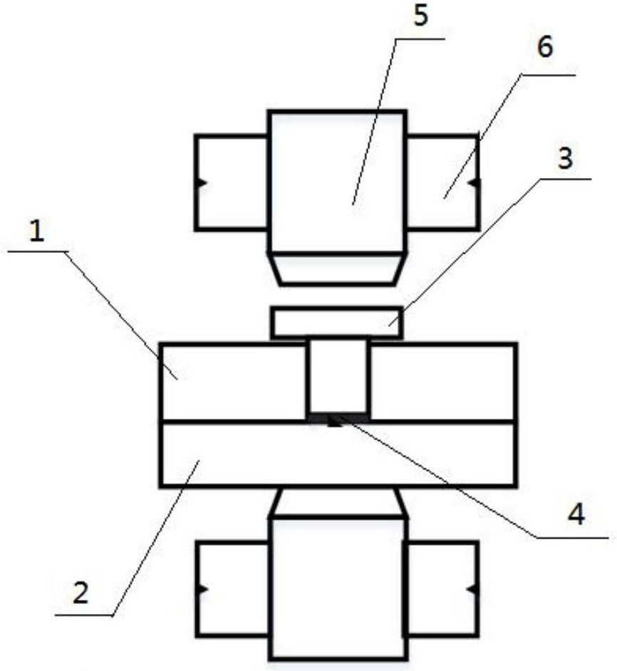
Resistance unit welding method of Ni element regulated and controlled magnetic field assisted aluminum alloy and steel
A technology of magnetic field assistance and welding method, which is applied in the direction of resistance welding equipment, welding equipment, metal processing equipment, etc., can solve the problems of poor bearing capacity of ferrite, increase of use cost, decline of weld structure and performance, etc., and achieve suppression of formation and Effects of segregation, increased uniformity, and enhanced overall performance
- Summary
- Abstract
- Description
- Claims
- Application Information
AI Technical Summary
Problems solved by technology
Method used
Image
Examples
specific Embodiment approach 1
[0040] A kind of magnetic field assisted aluminum alloy and steel resistance unit welding method regulated by Ni element comprises the following steps:
[0041] Step 1. Prepare the steel base material, aluminum alloy base material, rivets, and Ni foil to be welded, and make holes on the surface of the aluminum alloy base material to be welded for use;
[0042] Step 2. After degreasing and cleaning the steel base material to be welded, the aluminum alloy base material after the through hole, the rivet, and the Ni foil, air-dry and set aside;
[0043] Step 3. Fix the magnet on the electrode head of the resistance spot welding machine for use;
[0044] Step 4. Put the Ni foil between the aluminum alloy base material and the steel base material. After lapping, place the rivet in the through hole of the aluminum alloy. After pressing the rivet, Ni foil and steel base material, use step 3 to have The electrode head of the magnet is welded to the resistance unit.
[0045] In the me...
specific Embodiment approach 2
[0061] A kind of magnetic field assisted aluminum alloy and steel resistance unit welding method regulated by Ni element comprises the following steps:
[0062] Step 1. Prepare the steel base material, aluminum alloy base material, rivets, and Ni foil to be welded, and make holes on the surface of the aluminum alloy base material to be welded for use;
[0063] Step 2. After degreasing and cleaning the steel base material to be welded, the aluminum alloy base material after the through hole, the rivet, and the Ni foil, air-dry and set aside;
[0064] Step 3. Fix the magnet on the electrode head of the resistance spot welding machine for use;
[0065] Step 4. Put the Ni foil between the aluminum alloy base material and the steel base material. After lapping, place the rivet in the through hole of the aluminum alloy. After pressing the rivet, Ni foil and steel base material, use step 3 to have The electrode head of the magnet is welded to the resistance unit.
[0066] In the me...
specific Embodiment approach 3
[0077] A kind of magnetic field assisted aluminum alloy and steel resistance unit welding method regulated by Ni element comprises the following steps:
[0078] Step 1. Prepare the steel base material, aluminum alloy base material, rivets, and Ni foil to be welded, and make holes on the surface of the aluminum alloy base material to be welded for use;
[0079] Step 2. After degreasing and cleaning the steel base material to be welded, the aluminum alloy base material after the through hole, the rivet, and the Ni foil, air-dry and set aside;
[0080] Step 3. Fix the magnet on the electrode head of the resistance spot welding machine for use;
[0081]Step 4. Put the Ni foil between the aluminum alloy base material and the steel base material. After lapping, place the rivet in the through hole of the aluminum alloy. After pressing the rivet, Ni foil and steel base material, use step 3 to have The electrode head of the magnet is welded to the resistance unit.
[0082] In the met...
PUM
| Property | Measurement | Unit |
|---|---|---|
| thickness | aaaaa | aaaaa |
| thickness | aaaaa | aaaaa |
| thickness | aaaaa | aaaaa |
Abstract
Description
Claims
Application Information
 - R&D
- Intellectual Property
- Life Sciences
- Materials
- Tech Scout
- Unparalleled Data Quality
- Higher Quality Content
- 60% Fewer Hallucinations
Browse by: Latest US Patents, China's latest patents, Technical Efficacy Thesaurus, Application Domain, Technology Topic, Popular Technical Reports.
© 2025 PatSnap. All rights reserved.Legal|Privacy policy|Modern Slavery Act Transparency Statement|Sitemap|About US| Contact US: help@patsnap.com


