
Metal material machining waste treatment device

A technology for waste material treatment and metal materials, applied in metal processing equipment, grinding drive devices, grinding/polishing safety devices, etc., can solve the problems of unstable use, easy to dump, high risk factor, etc., and achieve fast and convenient use The effect of clamping

Inactive Publication Date: 2020-12-25
蚌埠知博自动化技术开发有限公司
View PDF10 Cites 0 Cited by
  • Summary
  • Abstract
  • Description
  • Claims
  • Application Information

AI Technical Summary

Problems solved by technology

[0004] Aiming at the deficiencies of the prior art, the present invention provides a metal material processing waste processing device, which solves the problems that the existing big data cloud computing all-in-one machine is unstable in use and prone to dumping, unsafe to use, and high risk factor

Method used


Image

  • Metal material machining waste treatment device
  • Metal material machining waste treatment device
  • Metal material machining waste treatment device

Examples


Embodiment 1

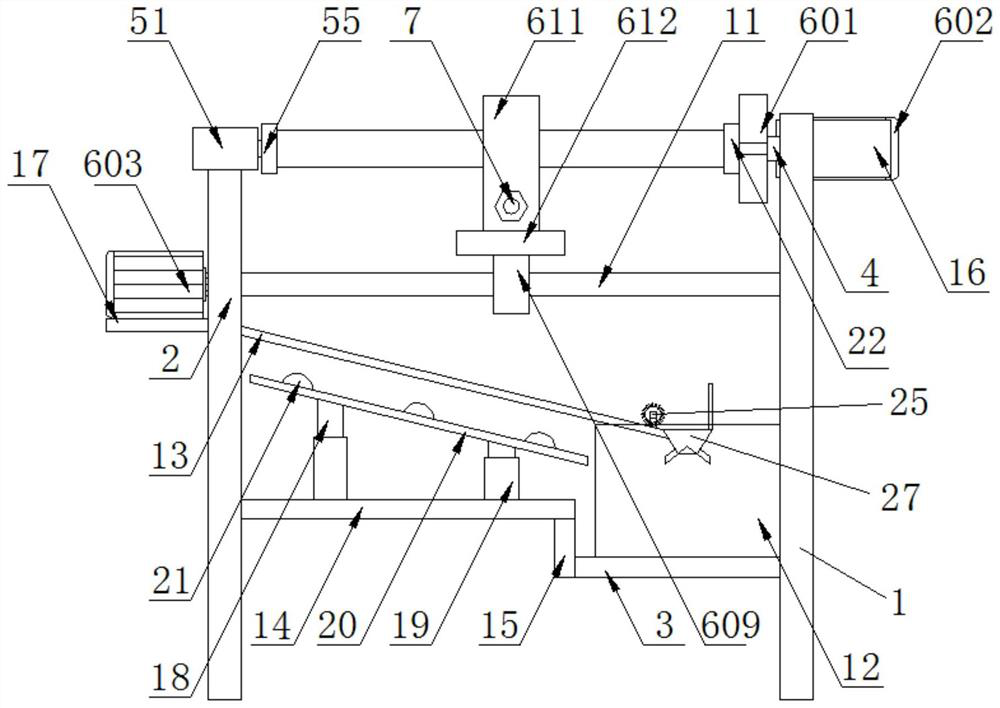
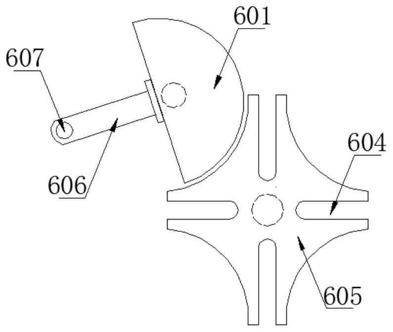
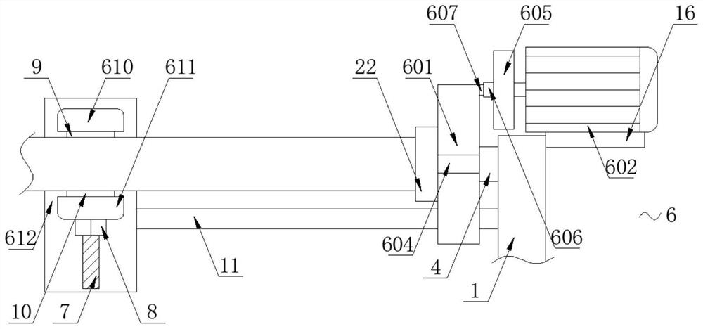
[0035] Including the first support plate 1 and the second support plate 2, one side of the first support plate 1 is fixedly connected with the first fixed plate 3, one side of the second support plate 2 is fixedly connected with the second fixed plate 14, the second fixed plate 1 The bottom of the plate 14 and the top of the first fixed plate 3 are fixedly connected by a vertical plate 15, one side of the first support plate 1 is rotatably connected with a support shaft 4, and the top of the second support plate 2 is provided with a clamping mechanism 5, The first support plate 1 and the second support plate 2 are provided with a polishing mechanism 6; the polishing mechanism 6 includes a rotating disc 601, a rotating motor 602 and a polishing motor 603, the polishing motor 603 is a three-phase asynchronous motor, and the outer surface of the rotating disc 601 is provided There is a card slot 604, the output end of the rotating motor 602 is fixedly connected with a rotating pla...

Embodiment 2

[0037] Including the first support plate 1 and the second support plate 2, one side of the first support plate 1 is fixedly connected with the first fixed plate 3, one side of the second support plate 2 is fixedly connected with the second fixed plate 14, the second fixed plate 1 The bottom of the plate 14 and the top of the first fixed plate 3 are fixedly connected by a vertical plate 15, one side of the first support plate 1 is rotatably connected with a support shaft 4, and the top of the second support plate 2 is provided with a clamping mechanism 5, The first support plate 1 and the second support plate 2 are provided with a polishing mechanism 6; the polishing mechanism 6 includes a rotating disc 601, a rotating motor 602 and a polishing motor 603, the polishing motor 603 is a three-phase asynchronous motor, and the outer surface of the rotating disc 601 is provided There is a card slot 604, the output end of the rotating motor 602 is fixedly connected with a rotating pla...

Embodiment 3

[0042] Including the first support plate 1 and the second support plate 2, one side of the first support plate 1 is fixedly connected with the first fixed plate 3, one side of the second support plate 2 is fixedly connected with the second fixed plate 14, the second fixed plate 1 The bottom of the plate 14 and the top of the first fixed plate 3 are fixedly connected by a vertical plate 15, one side of the first support plate 1 is rotatably connected with a support shaft 4, and the top of the second support plate 2 is provided with a clamping mechanism 5, The first support plate 1 and the second support plate 2 are provided with a polishing mechanism 6; the polishing mechanism 6 includes a rotating disc 601, a rotating motor 602 and a polishing motor 603, the polishing motor 603 is a three-phase asynchronous motor, and the outer surface of the rotating disc 601 is provided There is a card slot 604, the output end of the rotating motor 602 is fixedly connected with a rotating pla...


PUM


Abstract

The invention discloses a metal material machining waste treatment device. A polishing mechanism comprises a rotating disc, a rotating motor and a polishing motor, a clamping groove is formed in the outer surface of the rotating disc, a rotating plate is fixedly connected to the output end of the rotating motor, a guide rod is fixedly connected to the outer surface of the rotating plate, and a clamping rod is fixedly connected to one side of the outer surface of the guide rod. The invention relates to the technical field of metal machining. According to the metal material surface treatment device, a first clamping block and a second clamping block are used for clamping the surface of a copper pipe, the copper pipe intermittently rotates through intermittent rotation of the rotating plate,and then the polishing motor is used for driving a lead screw to do forward and reverse rotation motion, so that a moving plate moves back and forth; and the surface of the copper pipe can be polishedthrough the first clamping block and the second clamping block, and the problems that due to the fact that in an existing copper pipe polishing manner, time and labor are consumed, the working efficiency is low, meanwhile, the labor burden of workers is increased, and the large-scale treatment capacity in actual use is difficult to meet are solved.

Description

technical field [0001] The invention relates to the technical field of metal processing, in particular to a metal material processing waste processing device. Background technique [0002] Copper tubes are also called copper tubes. A type of non-ferrous metal pipe, which is a pressed and drawn seamless pipe. Copper pipe has good electrical conductivity and thermal conductivity, and is the main material of conductive accessories and heat dissipation accessories of electronic products, and has become the first choice for modern contractors to install tap water pipes, heating and cooling pipes in all residential commercial buildings. Copper tubes have strong corrosion resistance, are not easy to oxidize, and are not easy to chemically react with some liquid substances, and are easy to bend. Copper tubes are resistant to high temperatures and can be used in a variety of environments. Compared with this, the shortcomings of many other pipe materials are obvious. For example, t...

Claims


Application Information

Patent Timeline
IPC IPC(8): B24B29/08B24B27/00B24B41/06B24B47/00B24B47/12B24B47/16B24B47/22B24B55/06B24B55/12
CPCB24B27/0076B24B29/08B24B41/061B24B47/00B24B47/12B24B47/16B24B47/22B24B55/06B24B55/12
Inventor 常胜宝孟强
Owner 蚌埠知博自动化技术开发有限公司
Features
  • Generate Ideas
  • Intellectual Property
  • Life Sciences
  • Materials
  • Tech Scout
  • Unparalleled Data Quality
  • Higher Quality Content
  • 60% Fewer Hallucinations
Learn More