
Strip winding device, strip winding method and numerical control winding machine

A technology of winding device and winding machine, which is applied in the field of automatic molding of composite materials, can solve the problems of unsightly appearance of winding products, uneven thickness of products, and inability to realize stable control of cloth deformation, so as to reduce monitoring measures and ensure winding The effect of quality, structure simplification

Active Publication Date: 2020-12-25
SHANGHAI COMPOSITES SCI & TECH CO LTD
View PDF6 Cites 2 Cited by
  • Summary
  • Abstract
  • Description
  • Claims
  • Application Information

AI Technical Summary

Problems solved by technology

At present, woven fabric reinforced resin-based composite material prepreg tape winding has been wound by numerical control equipment. For example, the Chinese invention patent publication number is CN108327310A, which discloses an automatic winding equipment for the thermal insulation layer of a cylindrical composite shell and its use method , the automatic winding equipment involved in this invention only has tension-controlled winding, which cannot realize stable control of the deformation of the cloth tape, resulting in problems such as unsightly appearance of the wound product and uneven thickness of the product.

Method used


Image

  • Strip winding device, strip winding method and numerical control winding machine
  • Strip winding device, strip winding method and numerical control winding machine

Examples


Embodiment 1

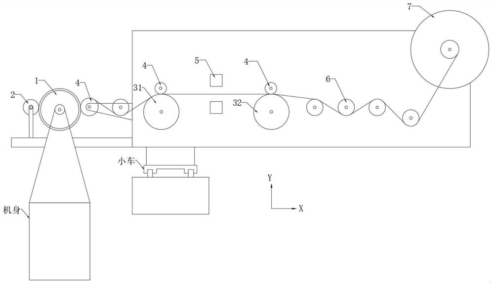
[0031] Such as Figure 1-2 As shown, the present invention provides a winding device based on a numerically controlled winding machine, including a mandrel 1 , a speedometer 2 , a traction assembly 3 , a pressing roller 4 , a width sensor 5 and an unwinding shaft 7 . The mandrel 1 acts as a winding power shaft, and the strip is wound on it through its regular rotation. Velocimeter 2 is used to measure the linear speed of the strip. The traction assembly 3 is used as an active traction device for adjusting the linear velocity of the strip to realize the adjustment of the deformation of the strip, mainly the adjustment of the width of the strip. The pressure roller 4 is used in cooperation with the mandrel 1 and the traction assembly 3, and the pressure roller 4 is also provided in other parts of the strip winding transmission route. The width sensor 5 is used to measure the time width of the acquisition strip. Unwind reel 7 in order to supply strip. specifically:

[0032] ...

Embodiment 2

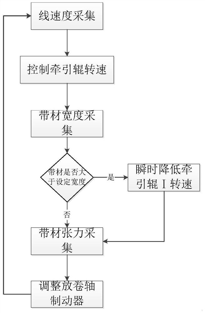
[0039] Such as Figure 1-2 As shown, this embodiment 2 is a strip winding method based on a numerically controlled winding machine formed on the basis of embodiment 1, which specifically includes the following steps:

[0040] S1, select the strip, preset the winding parameters of the strip, and start the operation program. The strip winding parameters include winding tension, spindle speed, strip deformation, strip width minimum deviation response value, and speed difference between the first pulling roller 31 and the second pulling roller 32 . Wherein preferably, the minimum deviation response value of the strip width is 1-3 mm, particularly preferably 2 mm.

[0041] S2, measuring and maintaining the linear velocity: obtain the linear velocity of the strip through the speedometer 2, and adjust the rotational speeds of the first pulling roller 31 and the second pulling roller 32 to be consistent with the linear velocity of the strip.

[0042]S3, strip deformation control: ad...


PUM


Abstract

The invention relates to the technical field of composite material automatic formation, in particular to a strip winding device. The strip winding device comprises a mandrel, a velometer, a traction assembly, press rolls, a width sensor and an unwinding shaft. The traction assembly comprises a first traction roller and a second traction roller. The mandrel, the first traction roller, the second traction roller and the unwinding shaft are sequentially arranged. The velometer makes contact with the mandrel, the width sensor is arranged between the first traction roller and the second traction roller, and the mandrel, the first traction roller and the second traction roller are respectively provided with the press rolls. The invention further provides a strip winding method and a numerical control winding machine thereof. According to the strip winding device, because the width sensor and the traction assembly are arranged at the near end of the strip winding mandrel, a deformed strip isadjusted and then enters the mandrel, the measures of monitoring on a middle conveying line of the strip can be greatly lessened, the device is simplified, and the efficiency is improved.

Description

technical field [0001] The invention relates to the technical field of automatic forming of composite materials, in particular to a strip winding device, a strip winding method and a numerically controlled winding machine. Background technique [0002] Due to the high specific modulus and specific strength of composite materials, and the advantages of the integration of structural design and manufacturing, composite materials are widely used in the aerospace field. With the continuous improvement of the reliability and quality requirements of the composite material product structure in the aerospace field, and the continuous improvement of the composite material forming process technology, the requirements for the performance, reliability and stability of the composite material preform in the intermediate link of composite material forming Getting harsher. As an important part of a rocket engine, the tape-wound thermal insulation layer is the key to the rocket's dynamic per...

Claims


Application Information

Patent Timeline
Patent Type & Authority Applications(China)
IPC IPC(8): B29C53/66B29C53/80B29C53/82
CPCB29C53/66B29C53/8008B29C53/8041B29C53/8016B29C53/821Y02E60/10
Inventor 李世成王志远惠效禹常舰苗雨晴沈辉李来福田杰张砚达陈志诚刘启抱贾娜谢钟清
Owner SHANGHAI COMPOSITES SCI & TECH CO LTD
Learn More