
Engine body delayed oil supply lubricating system

A technology for lubricating systems and bodies, applied in closed-circuit lubricating systems, lubricating engines, controlling lubricant pressure, etc., can solve problems such as inability to lubricate connecting rod journals, insufficient oil supply to bearing pads, and large oil cut-off angles, etc., to achieve Simple structure, low cost, and the effect of reducing pressure fluctuations

Pending Publication Date: 2020-12-25
GUANGXI YUCHAI MASCH CO LTD
View PDF1 Cites 3 Cited by
  • Summary
  • Abstract
  • Description
  • Claims
  • Application Information

AI Technical Summary

Problems solved by technology

This structure only has an oil storage tank on the upper bearing bush, and the oil cut-off angle of the connecting rod bush is relatively large in the top dead center area, which is easy to cause bush burning. Lubricate and dissipate heat from the connecting rod journal
[0005] The above two structures can ensure the normal lubrication of the engine in steady state operation, but for frequent start-stop conditions, due to the rapid deceleration of the engine from high speed, the oil supply to the bearing pads is insufficient, and abnormal wear of the bearing pads often occurs. When the engine stops suddenly, it will overheating

Method used


Image

  • Engine body delayed oil supply lubricating system
  • Engine body delayed oil supply lubricating system
  • Engine body delayed oil supply lubricating system

Examples


Embodiment 1

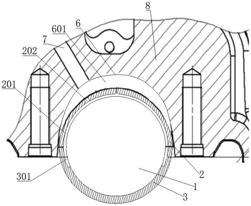
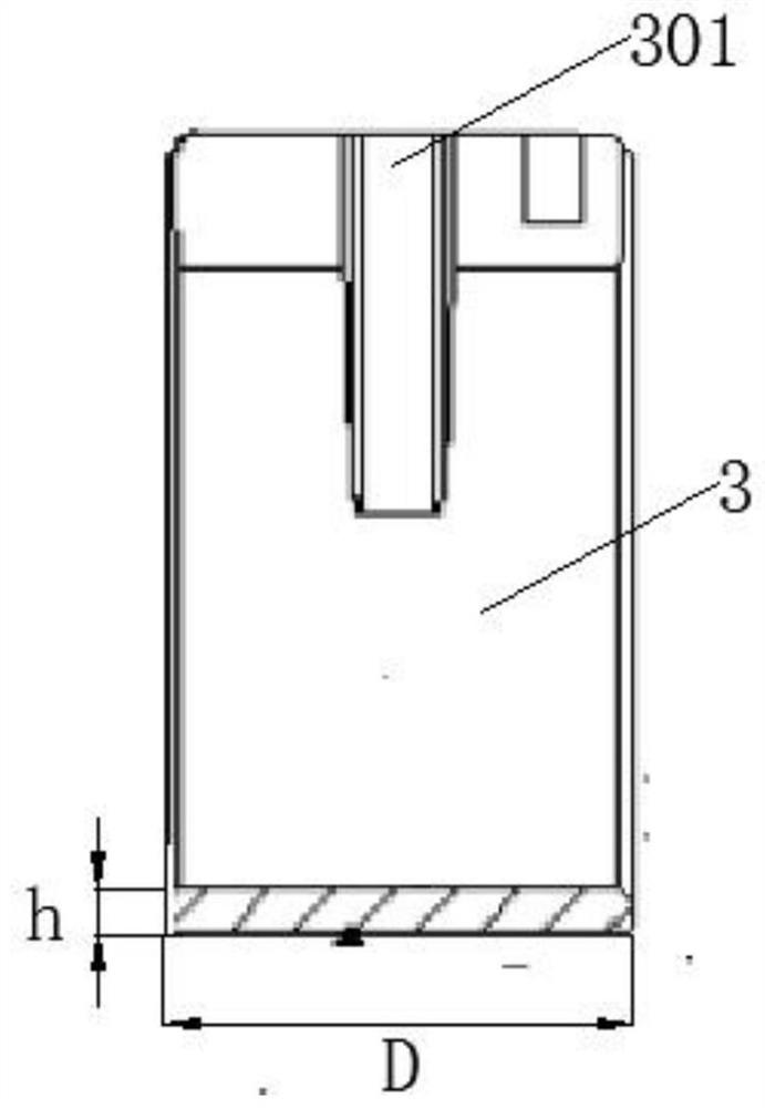
[0032] A body delay oil supply lubrication system, comprising a main journal 1, an upper bearing bush 2, a lower bearing bush 3, a journal oil passage 4 and a body 8, the upper bearing bush 2 is press-fitted on the upper part of the lower bearing bush 3, and the The body 8 is provided with a bearing seat 6 for installing the upper bearing bush 2, the journal oil passage 4 communicates with the main journal 1 and the connecting rod journal 5, an organic oil storage tank 601 is provided on the bearing seat, and the oil storage tank 601 of the body The oil groove 601 communicates with the main oil passage 7 on the machine body, and the upper oil storage tank 201 is arranged circumferentially on the inner peripheral surface of the upper bearing bush 2 . A lower oil storage tank 301 is arranged downward on the parting surface, and the lower oil storage tank 301 communicates with the end of the upper oil storage tank 201. The arc angle of the lower oil storage tank 301 is 25-35°. The...

Embodiment 2

[0036] Such as Figure 1~6 As shown, a delayed oil supply lubricating system for the machine body includes a main journal 1, an upper bearing shell 2, a lower bearing shell 3, a journal oil passage 4 and a machine body 8, and the upper bearing shell 2 is press-fitted on the upper part of the lower bearing shell 3 , the body 8 is provided with a bearing seat 6 for installing the upper bearing bush 2, and the journal oil passage 4 communicates with the main journal 1 and the connecting rod journal 5;

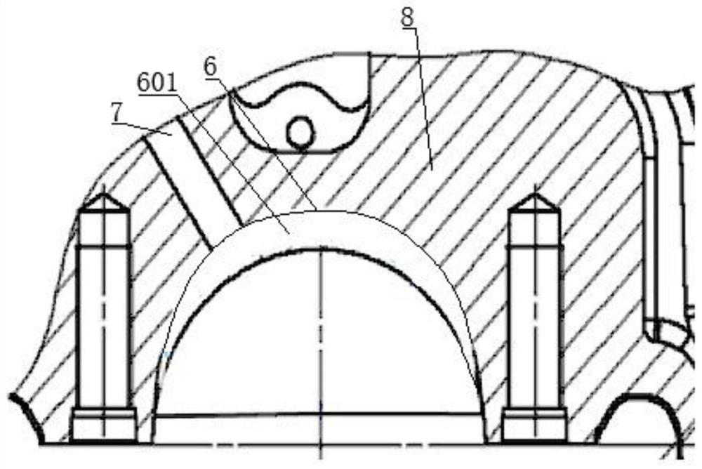
[0037] Such as figure 2 As shown, the bearing seat is provided with an organic oil storage tank 601, which communicates with the main oil passage 7 on the machine body, and an upper oil storage tank 201 is provided on the inner peripheral surface of the upper bearing bush 2 in the circumferential direction. On the inner circumference of the lower bearing bush 3, a lower oil storage tank 301 is arranged downward from the parting surface of the upper bearing bush 2. The lower oil st...

Embodiment 3

[0044] The difference between this embodiment and the above-mentioned embodiment 2 is: as image 3 The arc angle α where the lower oil storage tank 301 is located is 35°, which increases the oil supply continuation angle to the greatest extent, and the angle between the axis of the journal oil passage 4 and the vertical direction is viewed from the crankshaft axial direction β is 30°.


PUM


Abstract

The invention relates to an engine lubricating system, in particular to an engine body delayed oil supply lubricating system. The engine body delayed oil supply lubricating system comprises a main journal, an upper bearing bush, a lower bearing bush, a journal oil duct and an engine body; an engine body oil storage tank is formed in a bearing seat; a lower oil storage tank is downwards formed in the inner circumference of the lower bearing bush from the parting surface of the lower bearing bush and the upper bearing bush; and the tail ends of the lower oil storage tank and an upper oil storagetank are communicated. The engine body oil storage tank is additionally arranged in a bearing seat hole in the engine body, so that pressure attenuation is delayed; and oil tanks are formed in the left parting surface and the right parting surface of the lower bearing bush, so that the oil supply duration angle is increased, and bush burning faults are reduced.

Description

technical field [0001] The invention relates to an engine lubricating system, in particular to an engine body delayed oil supply lubricating system. Background technique [0002] The crankshaft oil supply system is generally connected by the main oil passage of the body and the bearing bush drilling. Generally, a long hole is drilled in the main bearing hole of the body to communicate with the main oil passage, and the oil in the main oil passage is guided to the crankshaft bearing hole. Crankshaft oil supply is generally provided by opening an oil groove on the upper bearing bush, drilling a hole in the crankshaft main journal, and leading the oil to the connecting rod journal for lubrication. The oil hole flows to the connecting rod journal. Lubricate, dissipate heat and flush the connecting rod journal. [0003] Such as the Chinese patent CN211175051U discloses a crankshaft thrust plate forced lubrication structure, including a body bearing seat and a bearing cap, the b...

Claims


Application Information

Patent Timeline
Patent Type & Authority Applications(China)
IPC IPC(8): F01M1/12F01M1/16F01M11/00F02F7/00
CPCF01M1/12F01M1/16F01M11/00F02F7/0065
Inventor 刘益军蒙小聪樊心龙罗威陈晓克
Owner GUANGXI YUCHAI MASCH CO LTD
Learn More